A high-efficiency heat dissipation power distribution cabinet

A power distribution cabinet, high-efficiency technology, applied in substation/distribution device housing, electrical components, substation/switch layout details, etc., can solve the problems of low space utilization, high temperature of internal accessories, poor heat dissipation function, etc. Improve heat dissipation efficiency and operational stability, increase the number of installations, and control the heat dissipation efficiency

Active Publication Date: 2021-04-13
东营市南方电器有限责任公司
View PDF10 Cites 0 Cited by
  • Summary
  • Abstract
  • Description
  • Claims
  • Application Information

AI Technical Summary

Problems solved by technology

[0003] At present, the outer box of the existing power distribution cabinet has poor heat dissipation function. When the factory uses the high and low voltage power distribution cabinet for a long time, it is easy to cause certain safety hazards due to the high temperature, which makes the internal parts damaged during operation.
[0004] Chinese patent (notification number CN208908315U) discloses a power distribution cabinet with ventilation and heat dissipation. Although it can perform ventilation and heat dissipation, the internal mechanism adopts an integrated installation structure, which has low space utilization, and the heat dissipation adopts a large channel blowing structure, which has low heat dissipation efficiency.

Method used


Image

  • A high-efficiency heat dissipation power distribution cabinet
  • A high-efficiency heat dissipation power distribution cabinet
  • A high-efficiency heat dissipation power distribution cabinet

Examples


Embodiment 1

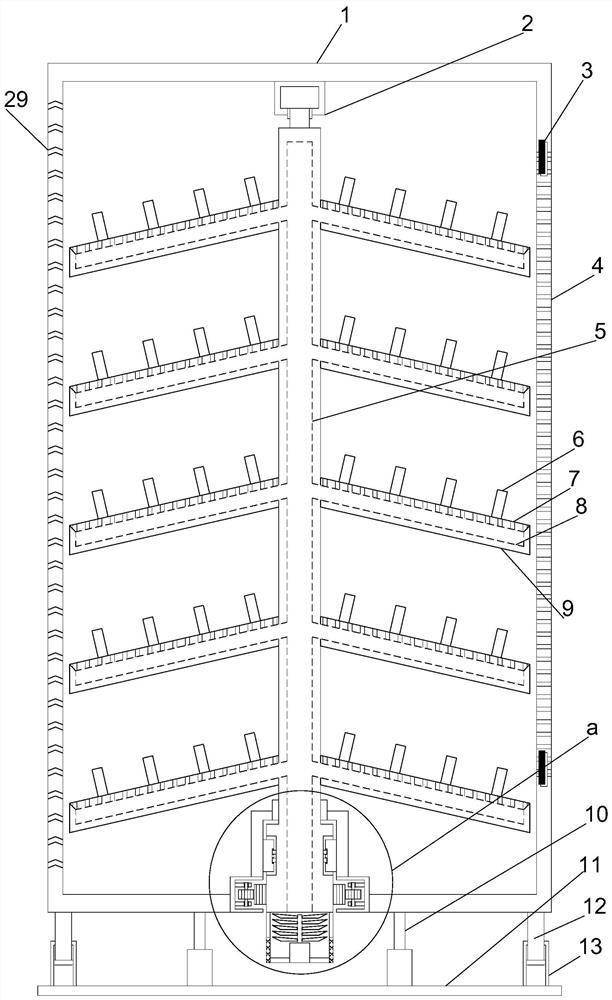
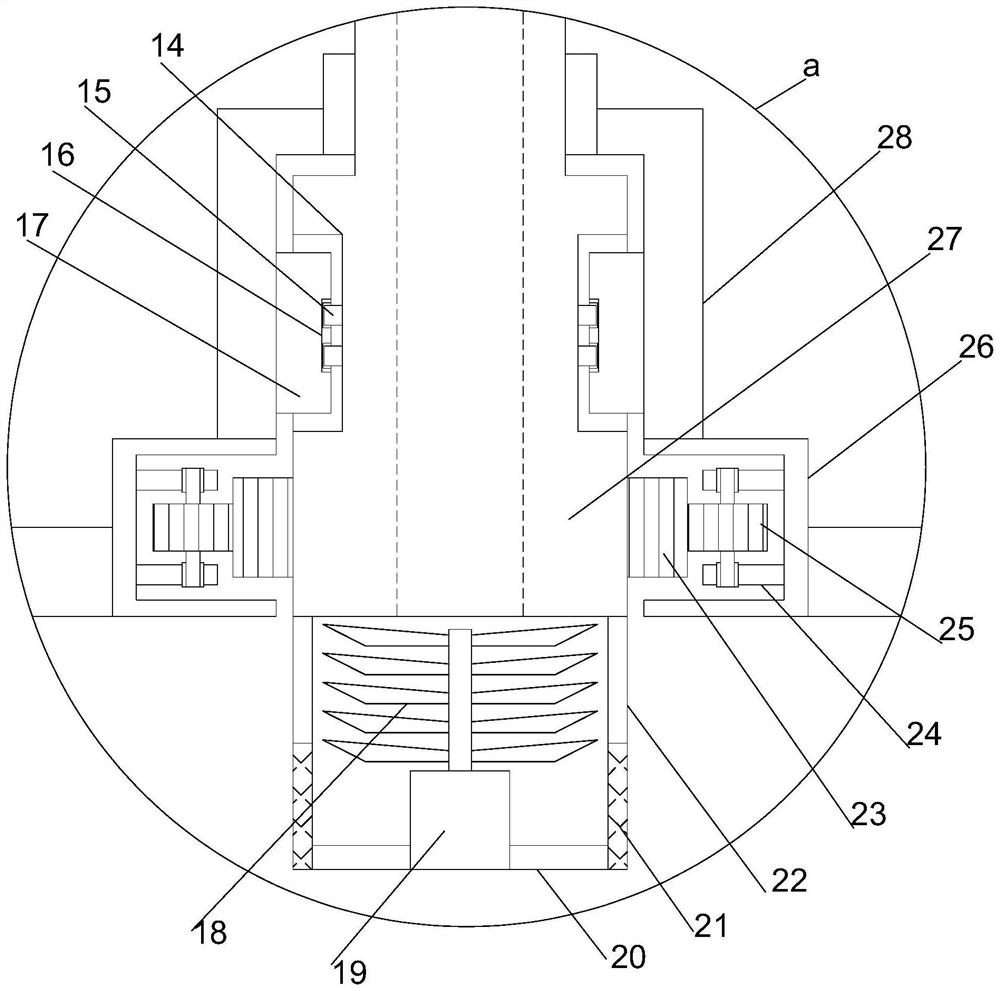
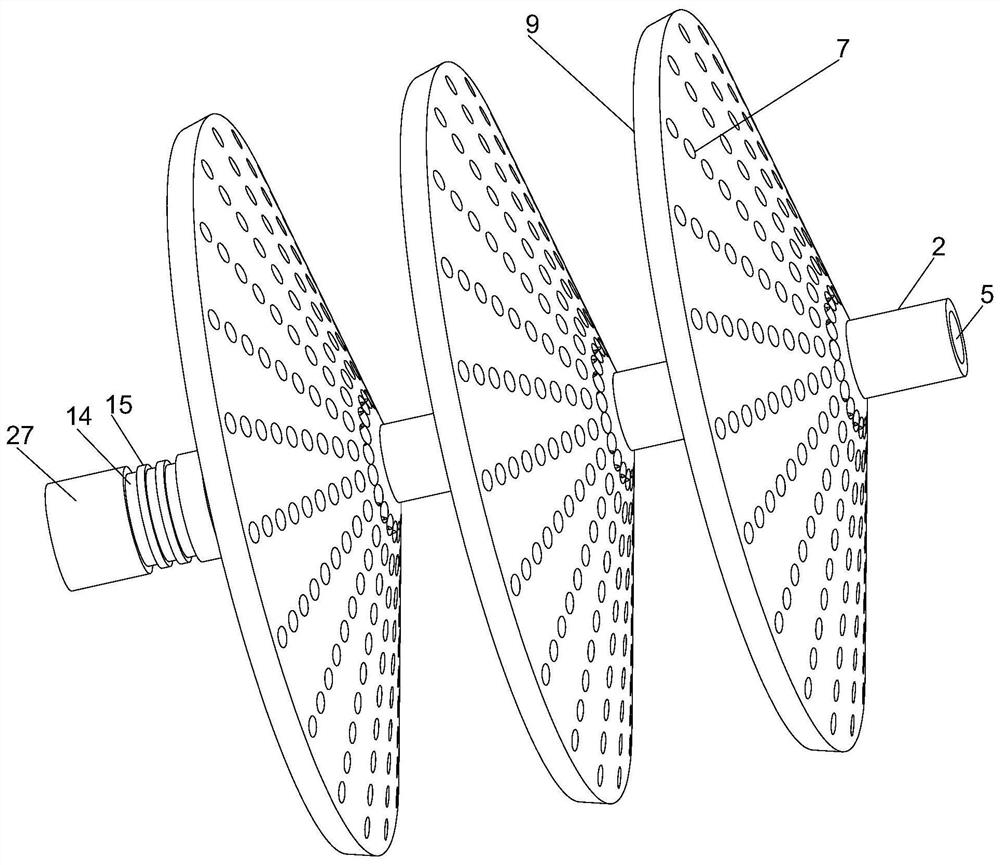
[0023] see Figure 1~3 , in the embodiment of the present invention, a high-efficiency heat dissipation power distribution cabinet includes a vertically arranged support installation cylinder 1, a support installation plate 11 is horizontally arranged directly below the support installation cylinder 1, and the right end of the support installation cylinder 1 is connected by a hinge 3 Rotation is provided with a rotating door 4, a number of heat dissipation holes 29 are evenly arranged on the wall of the supporting installation cylinder 1, and a limited rotation column 27 is vertically arranged in the inner middle position of the supporting installation cylinder 1, and the top of the supporting installation cylinder 1 cooperates with the limited rotation The column 27 is provided with a limit installation sleeve 2, and the heat dissipation holes 29 are bent. The bottom of the support installation cylinder 1 cooperates with the limit rotation column 27 to set a limit rotation ins...

Embodiment 2

[0026] On the basis of the first embodiment, the height of the supporting installation cylinder 1 can be changed stably by using the position-limiting support guide column 12 and the position-limiting support guide cylinder 13 in conjunction with the electric lifting column 10 to ensure the stable operation of the internal electronic components.


PUM


Abstract

The invention relates to the field of electric equipment, in particular to a high-efficiency heat dissipation power distribution cabinet, which includes a vertically arranged support installation cylinder, a support installation plate is horizontally arranged directly below the support installation cylinder, and the right end of the support installation cylinder is rotated by a hinge. For the rotating door, a number of heat dissipation holes are uniformly arranged on the wall of the supporting installation cylinder, a limited rotation column is vertically installed in the middle of the support installation cylinder, and a limited installation sleeve is arranged on the top of the support installation cylinder in conjunction with the limited rotation column. The multi-layer installation structure increases the number of power components installed in the device significantly, and the porous and uniform conduction conducts heat dissipation, and cooperates with the guide lifting structure to control the conduction of small steamed buns, so that the internal heat dissipation efficiency is controllable, and the axial rotation displacement, The power components inside the device can be quickly maintained, and the heat dissipation efficiency and operation stability of the power distribution cabinet are significantly improved.

Description

technical field [0001] The invention relates to the field of electric equipment, in particular to a high-efficiency heat dissipation power distribution cabinet. Background technique [0002] Power distribution cabinets (boxes) are divided into power distribution cabinets (boxes), lighting distribution cabinets (boxes), and metering cabinets (boxes), which are the final equipment of the power distribution system. The power distribution cabinet is a general term for the motor control center. The power distribution cabinet is used in the occasions where the load is relatively scattered and there are few circuits; the motor control center is used in the occasions where the load is concentrated and there are many circuits. They distribute the electric energy of a certain circuit of the upper-level power distribution equipment to the nearest load. This level of equipment shall provide protection, monitoring and control of the load. [0003] At present, the outer box of the exis...

Claims


Application Information

Patent Timeline
Patent Type & Authority Patents(China)
IPC IPC(8): H02B1/56H02B1/30H02B1/28
CPCH02B1/28H02B1/30H02B1/565
Inventor 张春红纪雯静陈秀美
Owner 东营市南方电器有限责任公司
Why Eureka
Try Eureka