
Gantry-type automatic spot welding system for battery pack

An automatic spot welding and gantry-type technology, applied in the direction of resistance welding equipment, welding equipment, metal processing equipment, etc., can solve the problems of enterprise loss, high welding labor intensity, unreliable welding, etc., to increase the number of installations and to reduce Labor intensity of workers, effect of improving spot welding efficiency and quality

Active Publication Date: 2014-06-04
FUJIAN NEBULA ELECTRONICS CO LTD
View PDF6 Cites 1 Cited by
  • Summary
  • Abstract
  • Description
  • Claims
  • Application Information

AI Technical Summary

Problems solved by technology

There are many defects in this method, which are mainly manifested in: 1. The welding labor intensity is high and the welding efficiency is low, and it is easy to cause worker fatigue
2. The dedicated spot welding power supply (expensive) has a high investment and a very low utilization rate, which greatly increases the cost of the enterprise
3. Welding is unreliable and easy to weld, resulting in a high scrap rate and poor reliability of the battery pack, causing huge losses to the enterprise
4. The welding appearance is not good, and the solder joints are prone to burrs, yellowing, blackening and other phenomena
5. The welding time is uncontrollable, which may easily cause changes in the internal resistance, voltage, and capacity of the battery cell, which will affect the performance of the battery cell
6. The operation safety is poor, and the manual welding sparks are more likely to cause explosions and other phenomena, which will affect the safety of workers
7. The position of the solder joint is not accurate, and manual operation cannot guarantee the uniform position of the solder joint
The spot welding devices of the above two patents have defects such as low welding pass rate, easy false welding, deformation of the battery core, bonding of welding needles, and uneven solder joints.

Method used


Image

  • Gantry-type automatic spot welding system for battery pack
  • Gantry-type automatic spot welding system for battery pack
  • Gantry-type automatic spot welding system for battery pack

Examples


Embodiment Construction

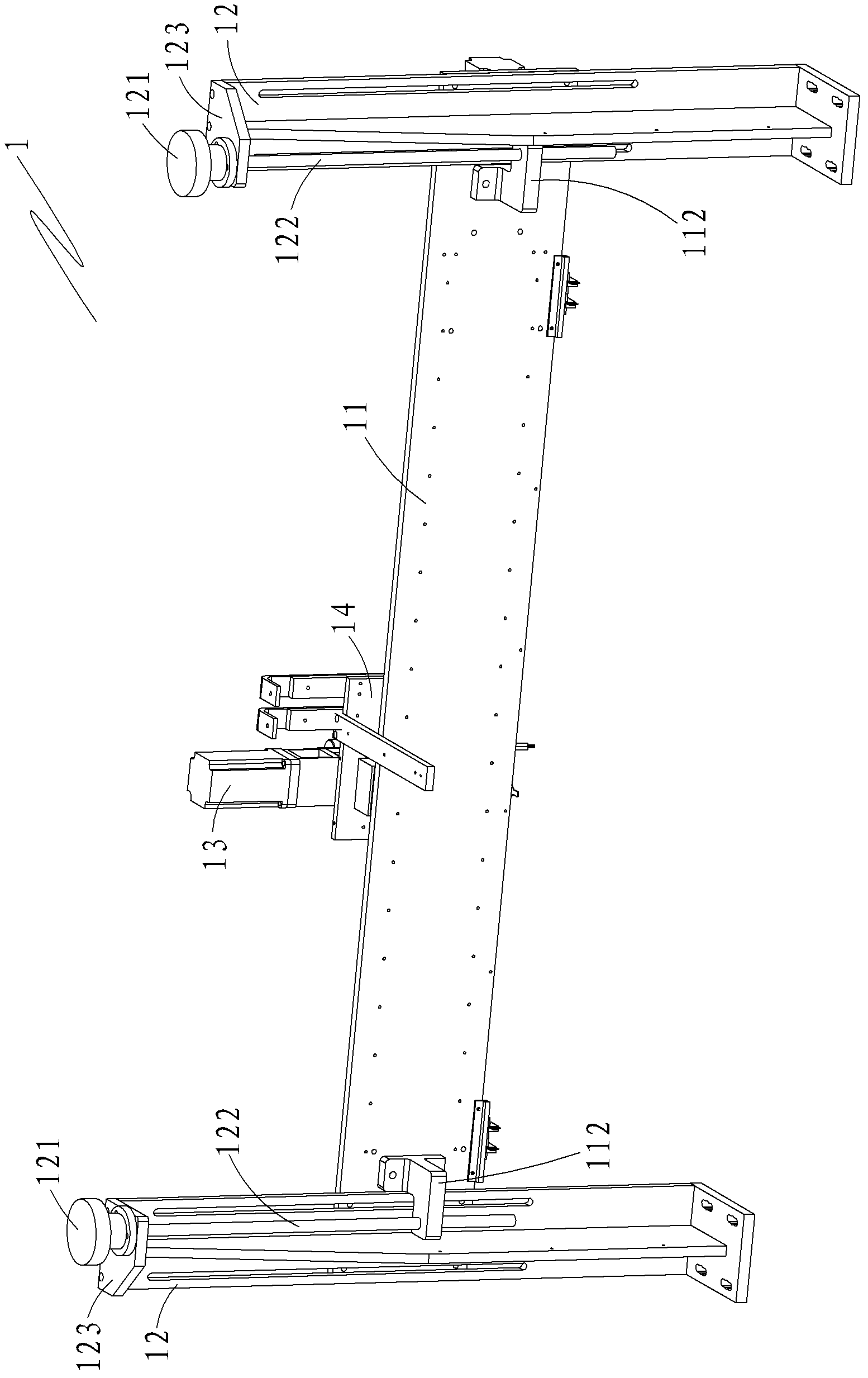
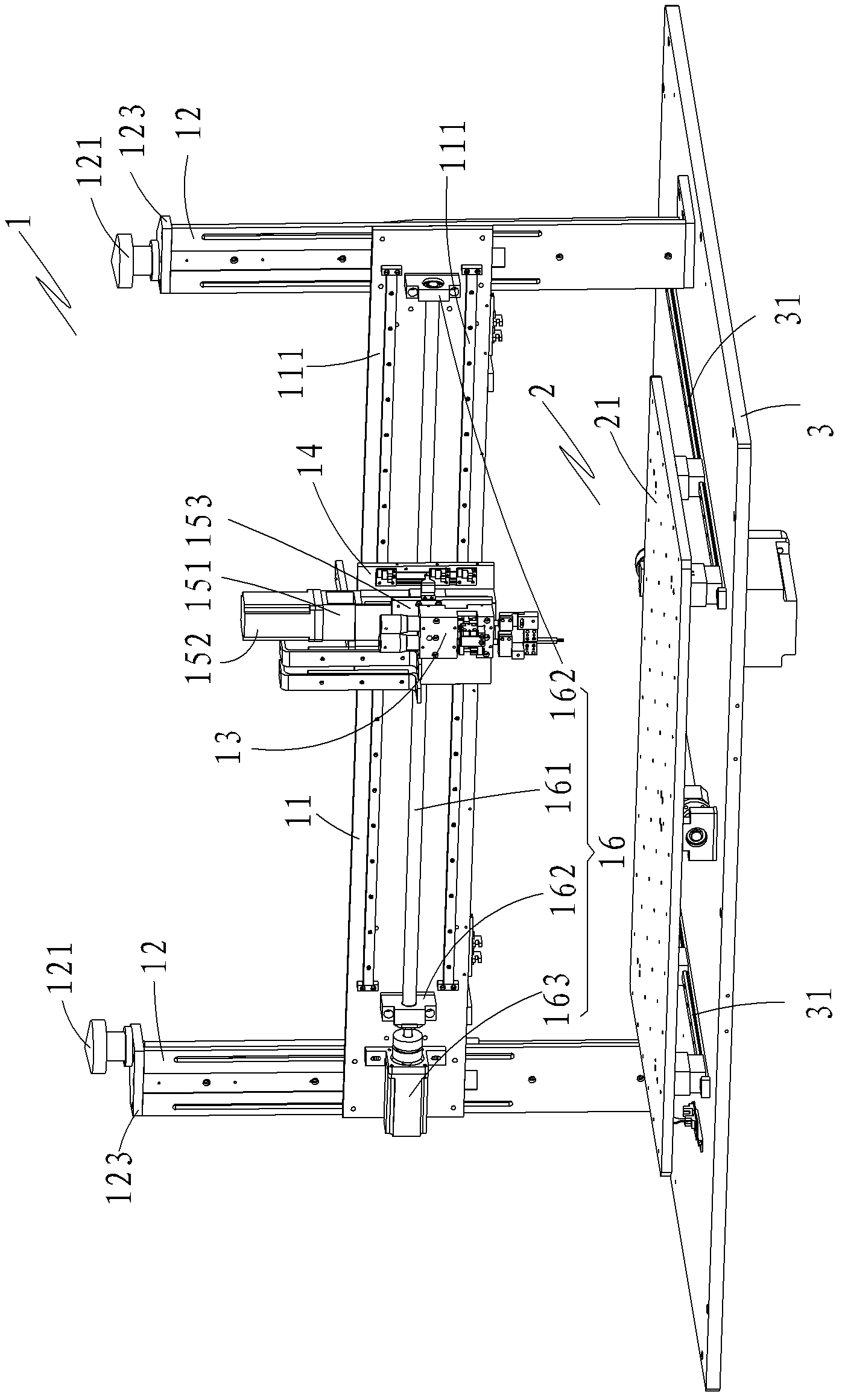
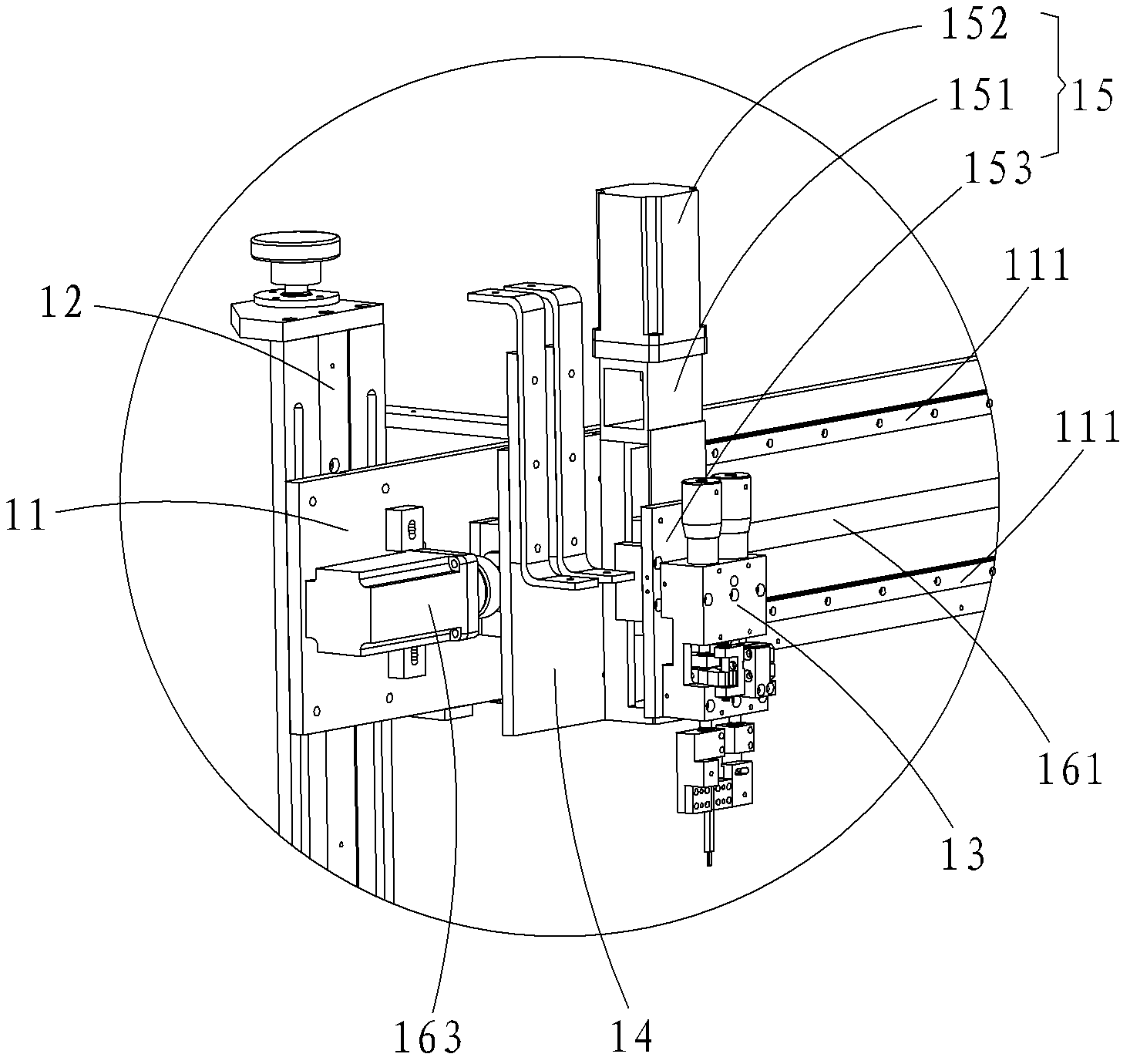
[0021] see figure 1 with figure 2 As shown, a gantry-type automatic spot welding system for a battery pack of the present invention includes a spot welding device 1 and a spot welding fixture fixing device 2 ( figure 1 The spot welding fixture fixing device is not shown); the spot welding device 1 includes a crossbeam 11, a group of columns 12, a spot welding mechanism 13 for fixing the point The X-axis slide table 14 of the welding mechanism 13, the Y-axis motion mechanism 15 that moves the spot welding mechanism 13 longitudinally, and the X-axis motion mechanism 16 that moves the X-axis slide table 14 laterally; the bottom of the beam 11 is arranged in parallel There are two guide rails 111, and a group of symmetrical beam fixing seats 112 are arranged on the surface of the beam 11, and the two beam fixing seats 112 are respectively slidably embedded in the column 12 through a screw rod 122 with a hand wheel 121, so as to It is beneficial for the crossbeam 11 to move on t...


PUM


Abstract

The invention provides a gantry-type automatic spot welding system for a battery pack, which comprises a spot welding device and a spot welding jig fixing device which are vertically arranged and are connected with a PLC (programmable logic controller) of the system. The spot welding device comprises a beam, a group of opposite vertical columns in parallel, a spot welding mechanism, an X-axis sliding table, a Y-axis movement mechanism and an X-axis movement mechanism, wherein the vertical columns are used for adjusting the height of the beam, the X-axis sliding table is used for fixing the spot welding mechanism, the Y-axis movement mechanism enables the spot welding mechanism to transversely move, and the X-axis movement mechanism enables the X-axis sliding table to transversely move. The spot welding jig fixing device comprises a spot welding jig platen and a clamping mechanism for clamping a spot welding jig, wherein the clamping mechanism is arranged on the spot welding jig platen and is perpendicular to the spot welding mechanism. By the aid of a gantry-type structure, clamping is performed once, cells are numerous, spot welding parameters are controllable, and the system is fast in running speed, high in spot welding efficiency, highly adaptable to the cells, accurate in positioning and fine in spot welding quality.

Description

【Technical field】 [0001] The invention relates to the technical field of automatic spot welding equipment for battery packs, in particular to a gantry-type automatic spot welding system for lithium batteries and power battery packs. 【Background technique】 [0002] The power battery pack is mainly used in electric vehicles, electric motorcycles and other fields. The battery cells used in the power battery pack are basically the same as other battery packs. The main feature is that the battery pack has a large capacity and a large number of battery cells. The difficulty is mainly It is reflected in the welding of the electric core. At present, most domestic manufacturers still adopt the traditional manual welding method. The specific operation is: 1. Pack the battery into the jig. 2. Install the nickel sheet. 3. Manual spot welding one by one. There are many defects in this mode, and it mainly shows in: 1, welding labor intensity is big and welding efficiency is low, and ve...

Claims


Application Information

Patent Timeline
Patent Type & Authority Patents(China)
IPC IPC(8): B23K11/11B23K11/36
Inventor 赖秋凤魏亚平郭金鸿许盛均
Owner FUJIAN NEBULA ELECTRONICS CO LTD
Learn More