
Electromagnetic shielding box

An electromagnetic shielding and electromagnetic switch technology, which is applied in the fields of magnetic/electric field shielding, electrical components, springs/shock absorbers, etc., can solve the problems of high manpower consumption, insufficient space in the transportation and placement of electronic equipment, and increased procurement costs of electromagnetic shielding boxes, etc. problem, to achieve the effect of improving the reasonable utilization rate

Pending Publication Date: 2021-08-03
东台市苏宝电磁屏蔽设备有限公司
View PDF0 Cites 0 Cited by
  • Summary
  • Abstract
  • Description
  • Claims
  • Application Information

AI Technical Summary

Problems solved by technology

[0003] The purpose of the present invention is to provide an electromagnetic shielding box for the shortcomings of the prior art, to solve the problem of the large structure of the existing electromagnetic shielding box proposed in the above background technology, especially the transportation and stacking of multiple electromagnetic shielding boxes , it is inconvenient to carry, and the manpower consumption is large. At the same time, the internal space of the existing electromagnetic shielding box is small, resulting in insufficient space during the transportation and placement of a large number of electronic equipment. At the same time, placing a large number of electronic equipment in batches will not only increase The number of placed electromagnetic shielding boxes also increases the purchase cost of electromagnetic shielding boxes

Method used


Image

  • Electromagnetic shielding box
  • Electromagnetic shielding box
  • Electromagnetic shielding box

Examples


Embodiment Construction

[0035] The following will clearly and completely describe the technical solutions in the embodiments of the present invention with reference to the accompanying drawings in the embodiments of the present invention. Obviously, the described embodiments are only some, not all, embodiments of the present invention. Based on the embodiments of the present invention, all other embodiments obtained by persons of ordinary skill in the art without making creative efforts belong to the protection scope of the present invention.

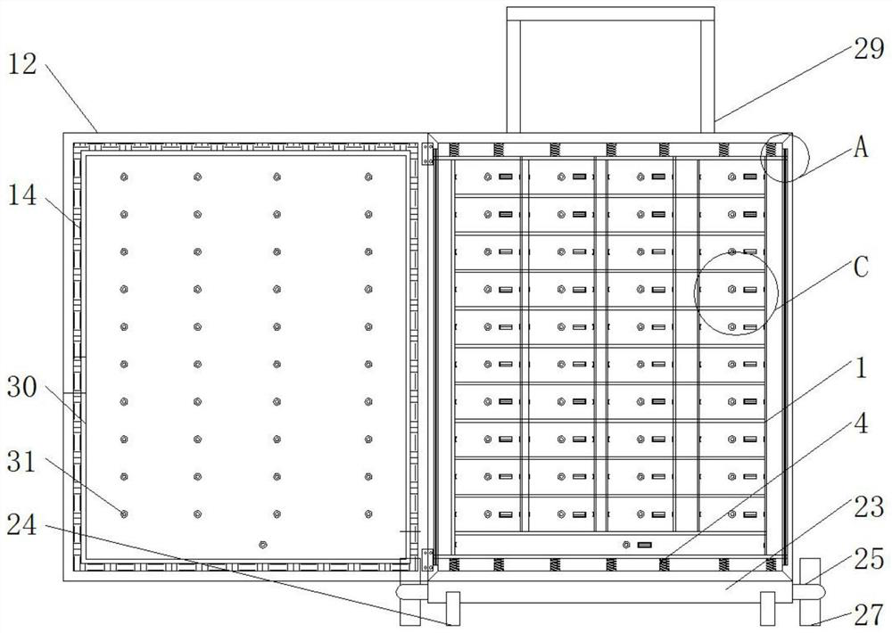
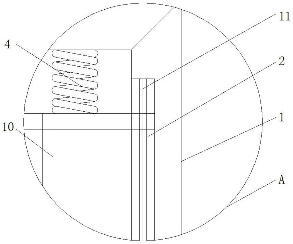
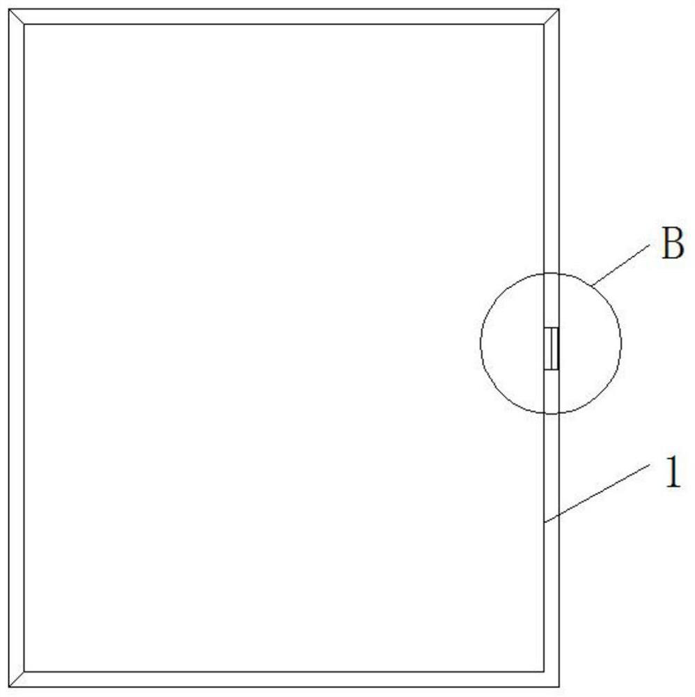
[0036] see Figure 1-11 , the present invention provides a technical solution: an electromagnetic shielding box, such as figure 1 , figure 2 , image 3 , Figure 4 , Figure 5 , Figure 6 , Figure 7 and Figure 8As shown, there are chute 2s on both sides of the inside of the box body 1, and a first installation groove 3 is opened on the right side of the box body 1, the top and bottom of the inside of the box body 1 are fixedly connected with the top ...


PUM


Abstract

The present invention discloses an electromagnetic shielding box which comprises a box body, a circuit board, a sliding rail, a sliding rod, a box door, an electromagnetic switch group, a control rod, a placement box, a placement plate, a connection block group, a telescopic pull rod and a mounting plate, sliding grooves are formed in two sides of the interior of the box body, a wave disturbance device is embedded and fixed on the surface of the circuit board, and the sliding rail is fixed in a mounting frame through a hexagon bolt. The sliding rod penetrates through the two sides of the mounting frame, the sliding rod is fixed into the box body through a sliding groove, the top end and the bottom of the mounting frame are fixedly connected with the top end and the bottom of a damping spring, a second mounting groove is formed in the left side of the box door in a penetrating mode, and an electromagnetic shielding layer is fixedly embedded in the front of the box door; and the right side of the box body is movably connected with the left side of the box body through a hinge, the electromagnetic shielding box is provided with the wave disturbances, and the multiple wave disturbances are used for carrying out wave disturbing processing on electronic equipment in the independent containing boxes, so that wave disturbing signals are increased, and the electromagnetic shielding effect of the whole box body is sequentially improved.

Description

technical field [0001] The invention relates to the technical field of electromagnetic shielding boxes, in particular to an electromagnetic shielding box. Background technique [0002] With the development of information technology, electronic devices have filled our lives. In daily office work and enterprise technology research and development, electronic devices are used more frequently. These electronic devices will emit electromagnetic waves under normal working conditions, resulting in the external environment. Searching for electronic devices can easily lead to leakage and theft of electronic device information, which will cause great harm. Therefore, it is necessary to shield the electromagnetic waves of individual electronic devices through electromagnetic shielding boxes, but the existing electromagnetic shielding boxes have a large structure , especially the transportation and stacking of multiple electromagnetic shielding boxes, which is inconvenient to carry and ...

Claims


Application Information

Patent Timeline
IPC IPC(8): H05K9/00F16F15/067
CPCF16F15/067H05K9/0007
Inventor 余彐东
Owner 东台市苏宝电磁屏蔽设备有限公司
Learn More