Storage battery charging and discharging device and charging and discharging method

A charging and discharging device and battery technology, which is applied to battery circuit devices, terminal battery switching devices, circuit devices, etc., can solve the problems of incapable of charging and discharging operation modules, and achieve the effect of easy portability and small system.

Pending Publication Date: 2019-08-30
HUNAN UNIV OF TECH
View PDF5 Cites 0 Cited by
  • Summary
  • Abstract
  • Description
  • Claims
  • Application Information

AI Technical Summary

Problems solved by technology

[0008] Aiming at the shortcomings in the prior art, the present invention provides a storage battery charging and discharging device, which solves the unidirectional charging characteristics of the traditional energy storage module (discharging operation cannot be performed in the charging state or the module is in the discharging state). Cannot perform charging operation)

Method used


Image

  • Storage battery charging and discharging device and charging and discharging method
  • Storage battery charging and discharging device and charging and discharging method
  • Storage battery charging and discharging device and charging and discharging method

Examples


Embodiment 1

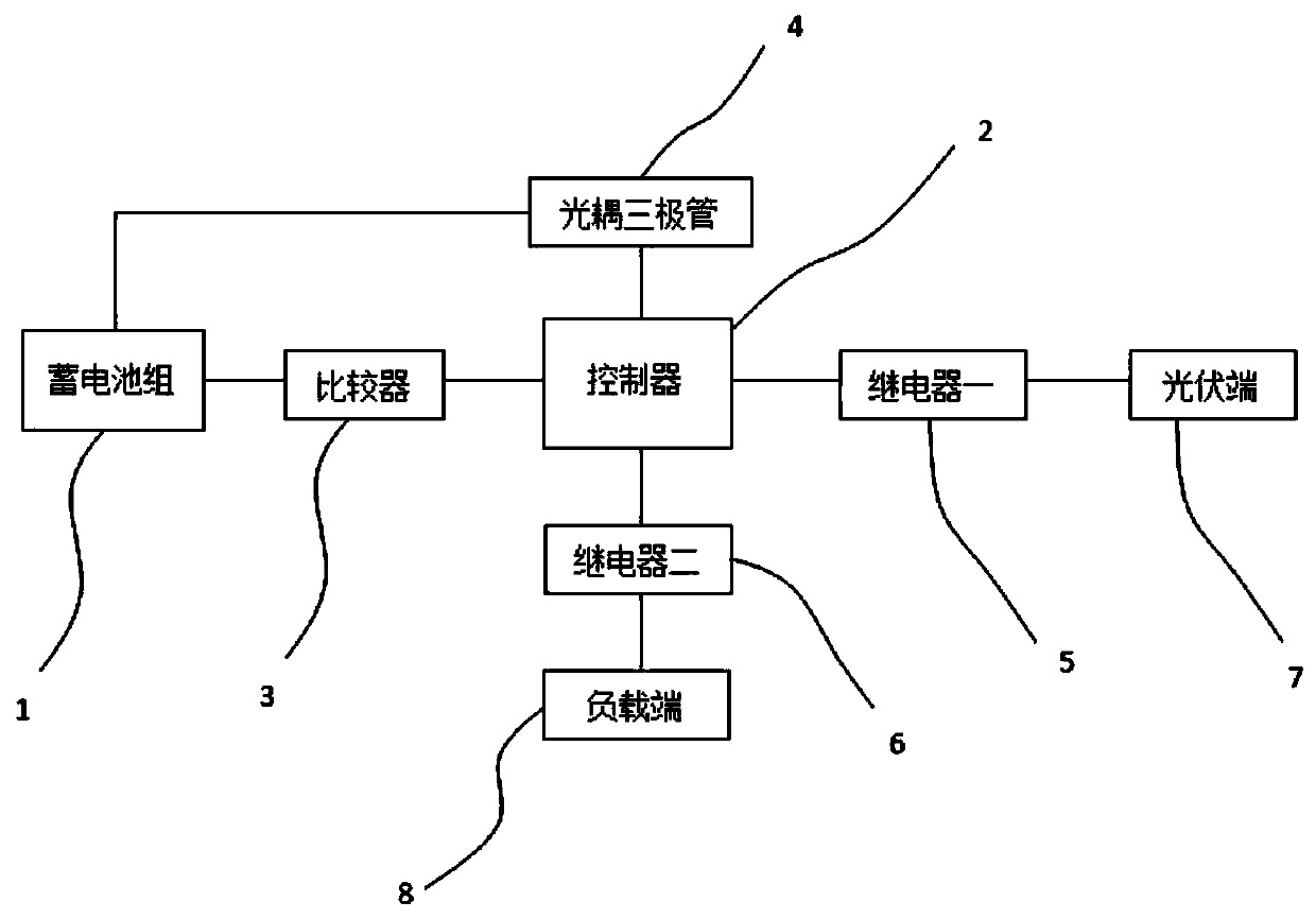
[0026] A storage battery charging and discharging device, such as the attached figure 1 As shown, it includes a storage battery pack 1, and the storage battery pack is provided with two, that is, a storage battery one and a storage battery two, and also includes a comparator 3, a controller 2, a charging and discharging device, and a power detection device 4; the controller 2 is used for Control the comparator 3, the power detection device 4 and the charging and discharging device; the comparator 3 is connected to the battery pack 1, and the comparator 3 is provided with a threshold voltage; the power detection device 4 is connected to the battery pack 1 for detecting the battery pack 1 battery power; the charging and discharging device includes a relay one 5, a relay two 6, and a photovoltaic terminal 7 and a load terminal 8 respectively connected to the two relays.

[0027] The relay one 5 is used to charge the battery pack, the normally open end and the normally closed end ...


PUM


Abstract

The invention relates to a storage battery charging and discharging device and method. The device comprises a plurality of storage batteries, a comparator, a controller, a charging and discharging device, and an electric quantity detection device. The controller is used for controlling the comparator, the detection device and the charging and discharging device. The comparator is connected with the storage battery and is provided with threshold voltage. The electric quantity detection device is connected with the storage batteries and used for detecting the electric quantity of the storage batteries. The charging and discharging device comprises two relays, a power generation device and a power supply load, wherein the power generation device and the power supply load are respectively connected with the two relays. The device has the working characteristic of 'charging and discharging at the same time'.

Description

technical field [0001] The invention relates to the field of storage batteries, in particular to a charging and discharging device for storage batteries. Background technique [0002] Generally, the control strategy adopted by traditional energy storage modules is bidirectional DC / DC converter control. In the bidirectional DC / DC converter control circuit, the energy storage unit charging and discharging reference current i ref Compared with the actual working current i, the generated error is sent to the PI controller. By limiting the output of the PI controller, the working current of the energy storage element is limited to avoid damage to the switch tube. The output value of the PI controller generates a driving pulse through a pulse width modulation (PWM) circuit to control the switching tube T in the bidirectional DC / DC converter. 1 , T 2 on and off. In the control process, the operation mode of the bidirectional DC / DC converter is determined by judging the positive...

Claims


Application Information

Patent Timeline
Patent Type & Authority Applications(China)
IPC IPC(8): H02J7/00H02J7/36H02J7/35
CPCH02J7/0068H02J7/36H02J7/35
Inventor 曾进辉易宗澳兰征刘京华一飞
Owner HUNAN UNIV OF TECH
Why Eureka
Try Eureka