IQ signal phase error control method and system

A signal phase and error control technology, applied in transmission systems, electromagnetic wave transmission systems, electromagnetic receivers, etc., can solve problems such as large computing loads, increased DSP power consumption, and inability to eliminate performance degradation of coherent optical communication systems, achieving low cost , the effect of low power consumption

Active Publication Date: 2019-08-30
FENGHUO COMM SCI & TECH CO LTD +2
View PDF7 Cites 3 Cited by
  • Summary
  • Abstract
  • Description
  • Claims
  • Application Information

AI Technical Summary

Problems solved by technology

However, in practical applications, due to the existence of influencing factors such as noise and dispersion, the compensation range of the algorithm is restricted
At the same time, the algorithm introduces a large calculation load, increases DSP power consumption, and great

Method used


Image

  • IQ signal phase error control method and system
  • IQ signal phase error control method and system
  • IQ signal phase error control method and system

Examples


Embodiment Construction

[0055] The present invention will be described in further detail below in conjunction with the accompanying drawings and embodiments.

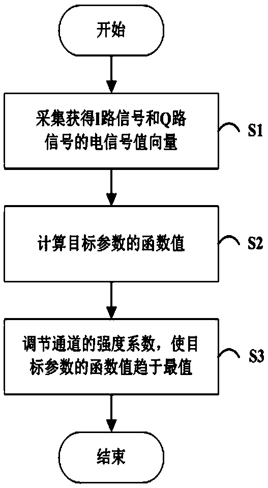
[0056] An embodiment of the present invention provides a method for controlling an IQ signal phase error, the method comprising the following steps:

[0057] By adjusting the intensity coefficients of channels corresponding to the I-channel signal and the Q-channel signal, the control of the phase error of the IQ signal is realized.

[0058] In this embodiment, the electrical signal values ​​of the I-channel signal and the Q-channel signal are changed by adjusting the intensity coefficient of the channel corresponding to the I-channel signal and the Q-channel signal, thereby affecting the phase error of the IQ signal to achieve control IQ signal phase error purposes.

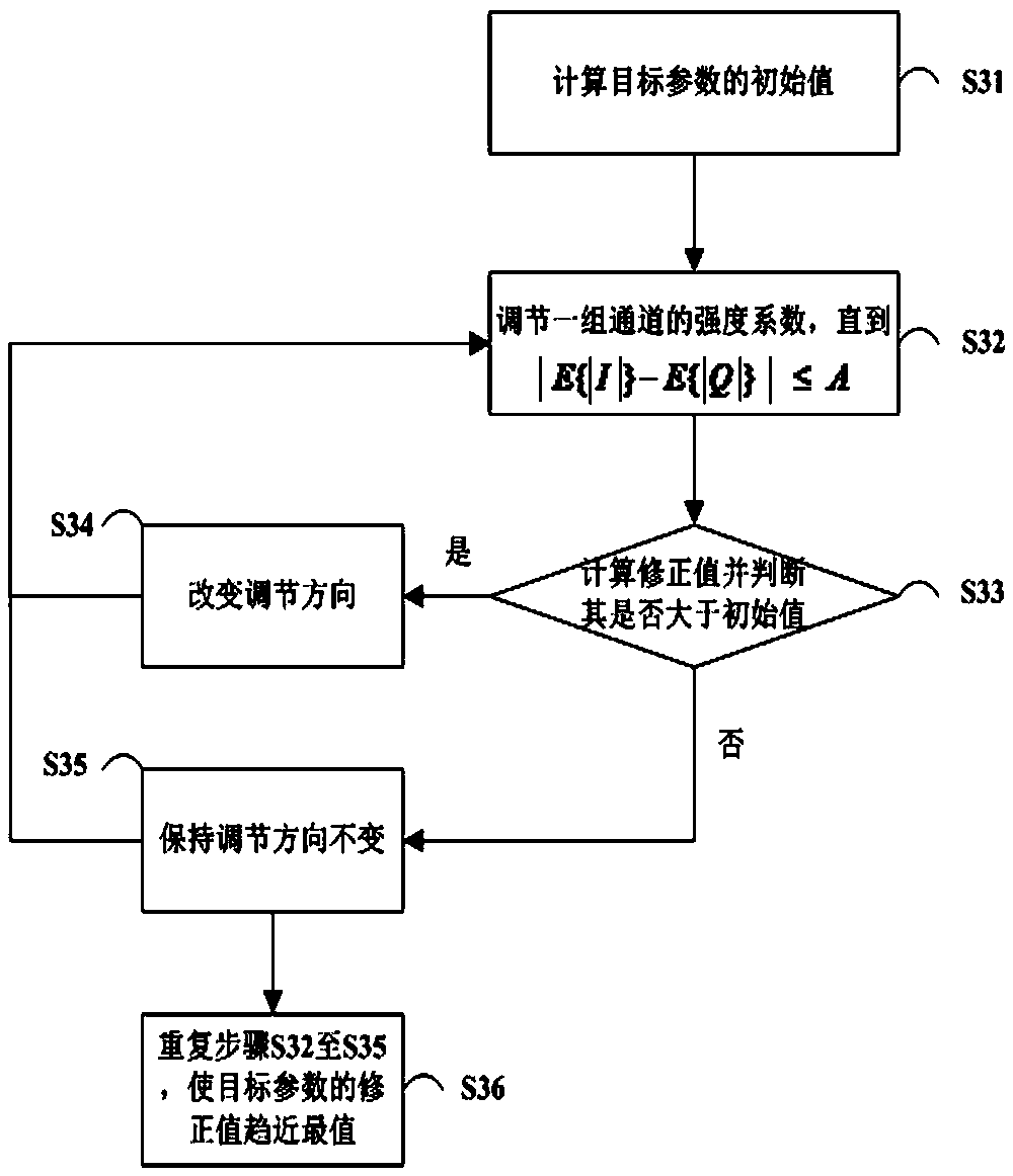
[0059] Specifically, see figure 1 As shown, by adjusting the intensity coefficient of the channel corresponding to the I-channel signal and the Q-channel signal, the control ...


PUM


Abstract

The invention discloses an IQ signal phase error control method and system, and relates to the technical field of coherent optical modules, and the method comprises the following steps: achieving thecontrol of an IQ signal phase error through adjusting the intensity coefficient of a channel corresponding to an I-path signal and a Q-path signal. According to the method, a phase shifter is not needed, the orthogonal angle phase error of the IQ signal can be reduced or even eliminated under the condition that an original coherent optical communication system architecture is not changed, and theperformance of the coherent optical communication system is improved.

Description

technical field [0001] The invention relates to the technical field of coherent optical modules, in particular to a method and system for controlling phase errors of IQ signals. Background technique [0002] In a coherent optical communication system, in order to utilize the phase information of light, I and Q modulation and demodulation are performed on the signal, which can greatly improve the capacity and distance of the coherent optical communication system. Coherent receivers use key components such as optical mixers to demodulate mutually orthogonal I and Q signals. [0003] However, in the actual demodulation process, due to certain process errors in the device, the demodulated I and Q signals are not perfectly quadrature, and there is a quadrature angle phase error (referred to as phase error), which reduces the demodulation performance and deteriorates the system performance. , such as the optical signal-to-noise ratio (OSNR). Moreover, the communication rate and ...

Claims


Application Information

Patent Timeline
IPC IPC(8): H04B10/61
CPCH04B10/6165
Inventor 朱石超曹权
Owner FENGHUO COMM SCI & TECH CO LTD
Why Eureka
Try Eureka