Method and arrangement for correcting phase error in linearization loop of power amplifier
A power amplifier and phase error technology, applied in the field of linearized power amplifiers, can solve problems such as spectrum expansion, phase shifter discontinuity, and linear loop instability
- Summary
- Abstract
- Description
- Claims
- Application Information
AI Technical Summary
Problems solved by technology
Method used
Image
Examples
Embodiment Construction
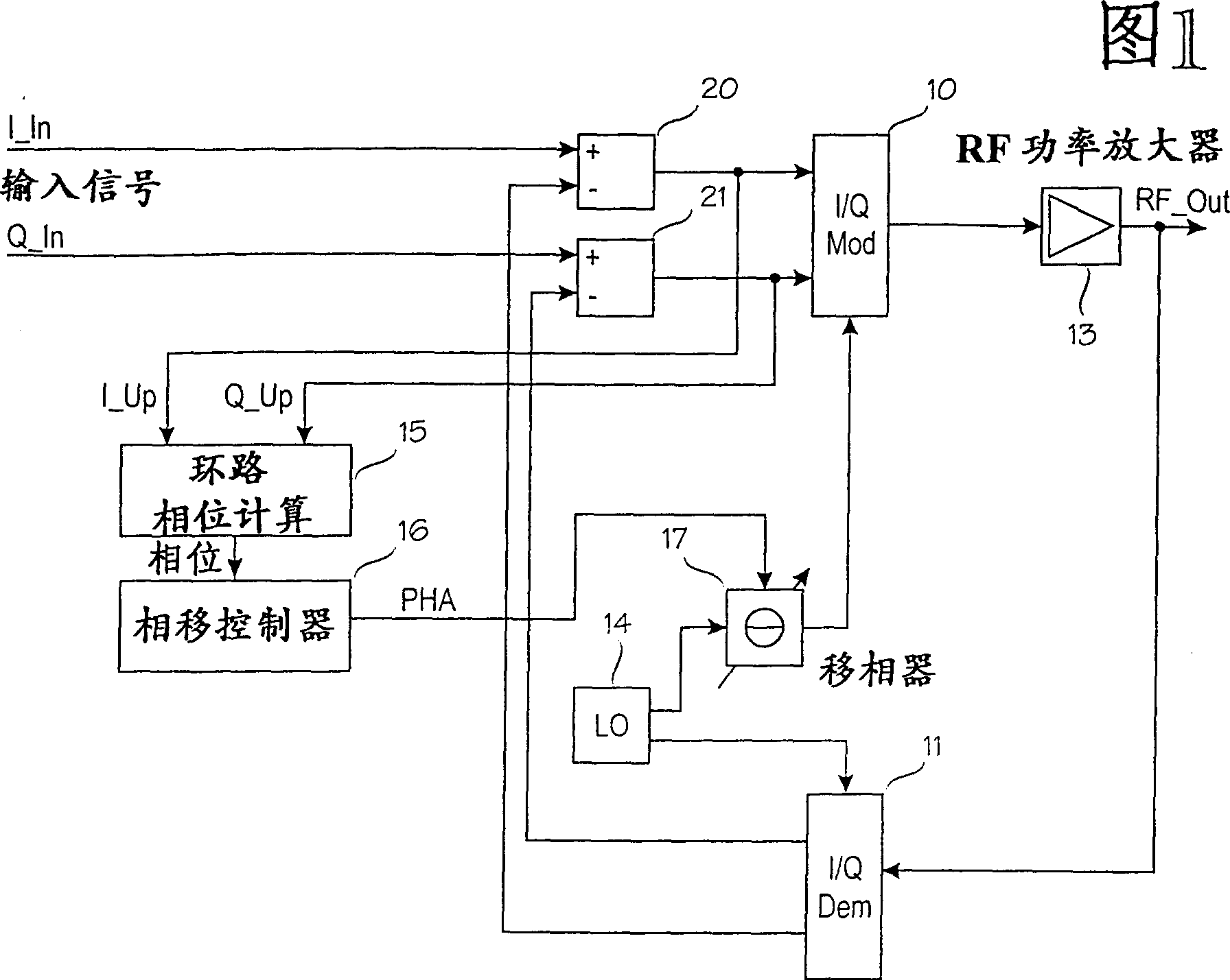
[0016] The linearization equipment of the transmitter power amplifier according to FIG. 1 roughly includes: an I / Q modulator 10, an I / Q demodulator 11, at least one power amplifier 13 that needs to be linearized, a local oscillator 14, and a loop phase calculation unit 15. Phase shift controller 16 and phase shifter 17. The I / Q modulator 10 and the I / Q demodulator 11 work on the principle of quadrature modulation. This allows two different signals to be combined in the transmitter, sent on the same transmission frequency band, and separated again in the receiver. The principle of quadrature modulation is to modulate two different signals, I and Q (in-phase and quadrature phase) with the same carrier frequency, but the carrier phases are different from each other. The carrier of signal Q is always 90° behind the carrier of signal I. After modulation, the signal accumulates. Because of the phase error, the signal I and Q can be separated during the demodulation and signal. In order ...
PUM
 Abstract
Description
Claims
Application Information
 - R&D
- Intellectual Property
- Life Sciences
- Materials
- Tech Scout
- Unparalleled Data Quality
- Higher Quality Content
- 60% Fewer Hallucinations
Browse by: Latest US Patents, China's latest patents, Technical Efficacy Thesaurus, Application Domain, Technology Topic, Popular Technical Reports.
© 2025 PatSnap. All rights reserved.Legal|Privacy policy|Modern Slavery Act Transparency Statement|Sitemap|About US| Contact US: help@patsnap.com


