
a melting plate

A technology of welding and splicing discs, which is applied in the direction of instruments, fiber mechanical structures, optics, etc., can solve problems such as excessive bending loss and business impact, and achieve the effect of reducing interference

Active Publication Date: 2021-01-05
HUAWEI TECH CO LTD
View PDF6 Cites 0 Cited by
  • Summary
  • Abstract
  • Description
  • Claims
  • Application Information

AI Technical Summary

Problems solved by technology

During maintenance, if you want to move or take out a certain fusion protection sleeve 03 for maintenance, you need to take out the irrelevant fusion protection sleeve 03 installed above it, which will affect other unrelated cables (such as bending Excessive loss, etc.), which will have a certain impact on the business of other cables

Method used


Image

  • a melting plate
  • a melting plate
  • a melting plate

Examples


Embodiment Construction

[0040] Embodiments of the present invention will be described in detail below in conjunction with the accompanying drawings.

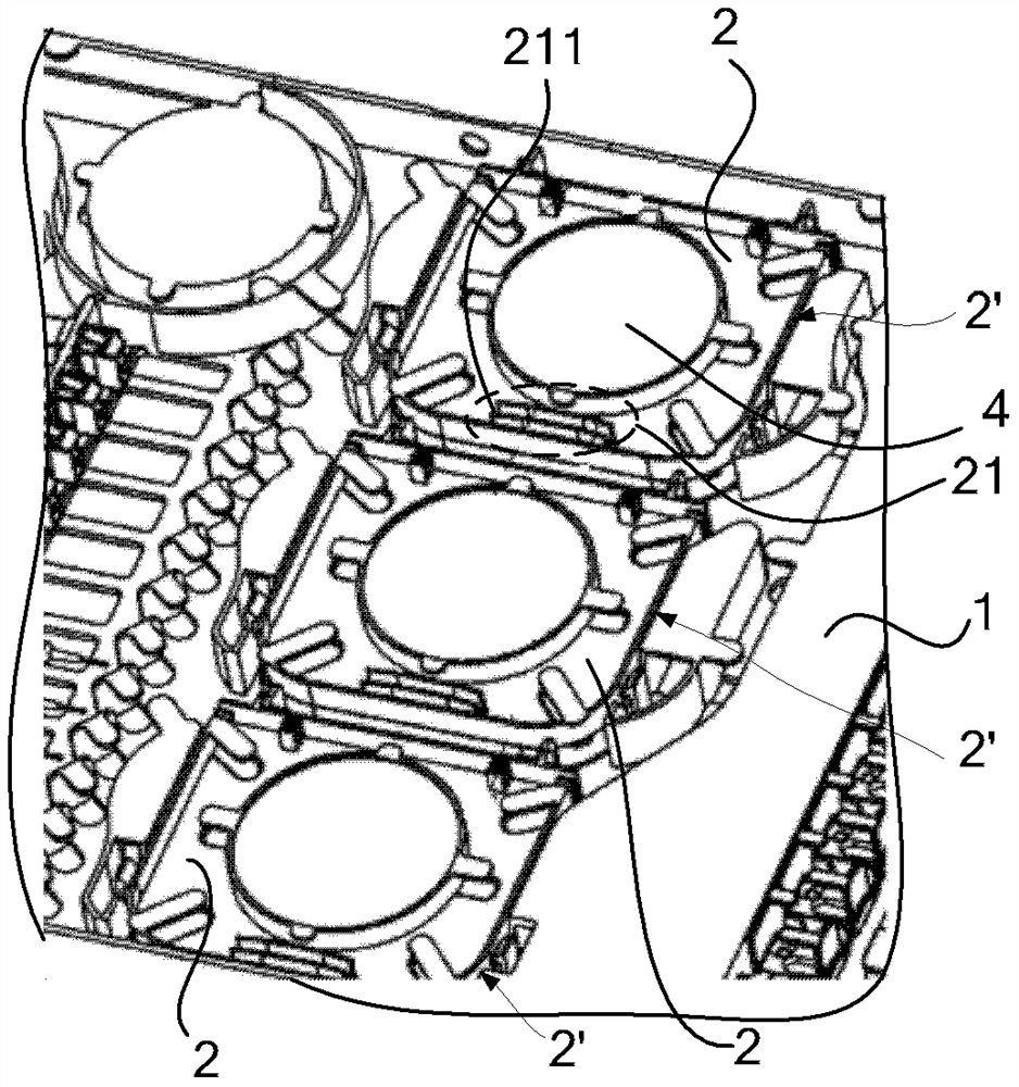
[0041] see image 3, the embodiment of the present invention provides a fusion splice tray, including a base 1, a plurality of fusion splice trays 2 independent of each other are provided on the base 1, the fusion splice tray 2 includes a fusion splice area 21, and one or more splice cards are arranged in the fusion splice area 21 Slot 211, a fusion splicing slot 211 is used to fix a line of cables to be fused.

[0042] Since the base 1 of the fusion splice tray provided in the embodiment of the present invention is provided with a plurality of fusion splice trays 2 that are independent of each other, and one or more fusion splicing slots 211 are provided in the fusing area 21 of the fusing tray 2, and one fusing splicing slot 211 It is used to fix a line of cables to be welded, so that the cables introduced into the splicing tray can be divided into ...


PUM

PropertyMeasurementUnit
Radiusaaaaaaaaaa

Abstract

A fusion splicing tray, relating to the technical field of optical fiber fusion, capable of isolating fusion splicing points in a fusion splicing area (21), and having little impact on other lines when maintaining one of the lines, thereby reducing the interference to other line services . The fusion splice tray includes a base (1), on which a plurality of fusion splice trays (2) independent of each other are arranged, and the fusion splice tray (2) includes a weld zone (21), and the weld zone ( 21) There are one or more welding slots (211) inside, and one of the welding slots (211) is used to fix a line of cables to be welded. This solution can be used for fusion splicing of optical fibers.

Description

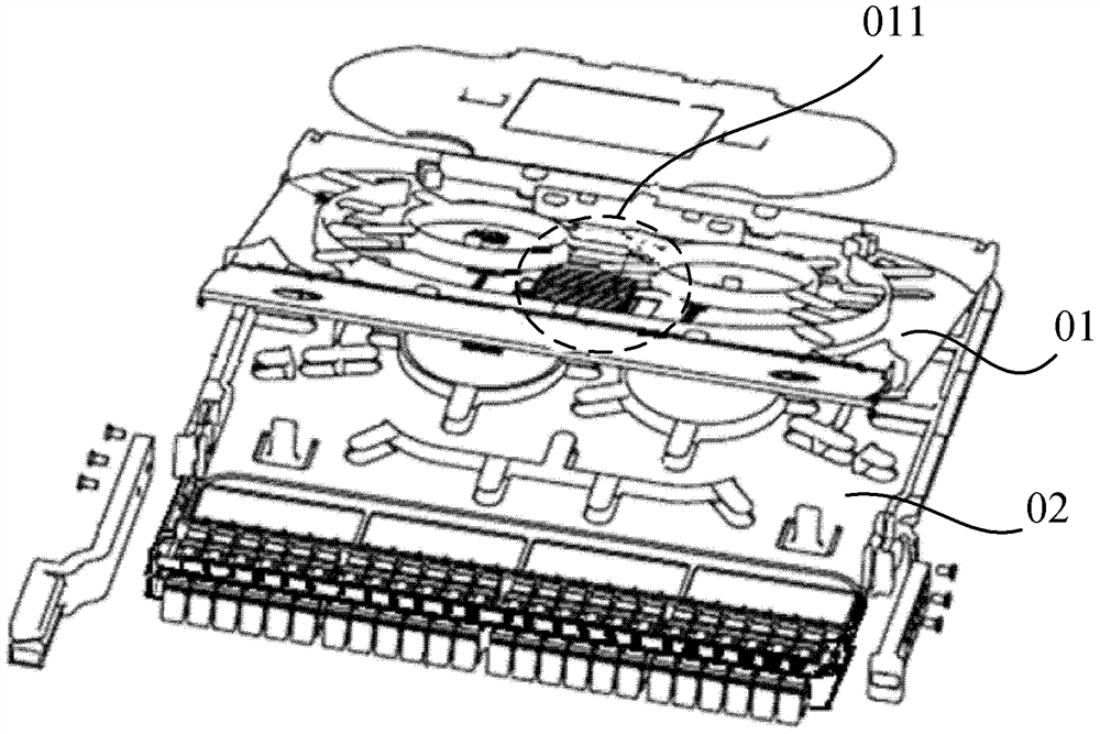
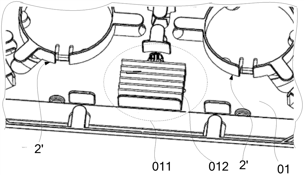
technical field [0001] The invention relates to the field of optical fiber fusion, in particular to a fusion tray. Background technique [0002] The splicing tray is mainly used for splicing and wiring of optical cables in optical cable transfer boxes and optical distribution frames. The traditional splicing tray structure is usually divided into upper and lower layers, the upper layer is welded, and the lower layer is wired and routed. The common capacity is 12 cores or 24 cores. [0003] An existing fusion plate, such as figure 1 and figure 2 As shown, it includes an upper welding tray 01 and a lower welding tray 02. The upper welding tray 01 is provided with a welding area 011. There are multiple welding slots 012 in the welding area 011. One welding slot 012 is used to fix a line to be welded. After the two cables are welded, a welding protective sleeve 03 is set at the welding point. [0004] In the existing fusion tray of this kind, the welding area 011 stores all...

Claims


Application Information

Patent Timeline
IPC IPC(8): G02B6/44G02B6/255
CPCG02B6/255G02B6/44G02B6/4455
Inventor 鄢宏宇熊伟王业仁舒思文
Owner HUAWEI TECH CO LTD
Learn More