A stamping die for rolled round parts

A technology of stamping die and buffer cavity, applied in the field of rolling round parts processing, can solve problems such as energy waste, and achieve the effects of convenient use, energy saving and simple equipment structure

Active Publication Date: 2021-02-26
GOLDBELL ELECTRIC DRIVES & CONTROLS SHENZHEN CO LTD
View PDF11 Cites 0 Cited by
  • Summary
  • Abstract
  • Description
  • Claims
  • Application Information

AI Technical Summary

Problems solved by technology

[0002] Rolled round parts are commonly used workpieces. When rolled round parts are used and scrapped, they can be recycled for secondary use. When recycling, firstly, the rolled round parts need to be collected, and then punched after collection. The existing rolled round parts are stamped The device often has a rolled piece thrown into the rolled piece cylinder to stamp the rolled piece, resulting in a waste of energy

Method used


Image

  • A stamping die for rolled round parts
  • A stamping die for rolled round parts
  • A stamping die for rolled round parts

Examples


Embodiment Construction

[0017] All features disclosed in this specification, or steps in all methods or processes disclosed, may be combined in any manner, except for mutually exclusive features and / or steps.

[0018] Any feature disclosed in this specification (including any appended claims, abstract and drawings), unless expressly stated otherwise, may be replaced by alternative features which are equivalent or serve a similar purpose. That is, unless expressly stated otherwise, each feature is one example only of a series of equivalent or similar features.

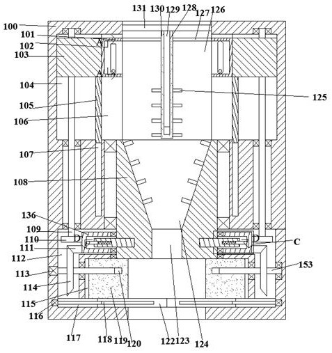
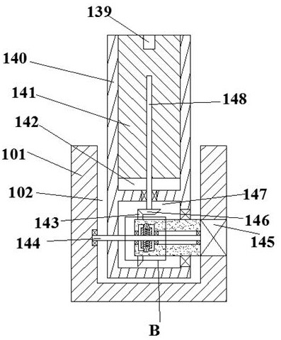
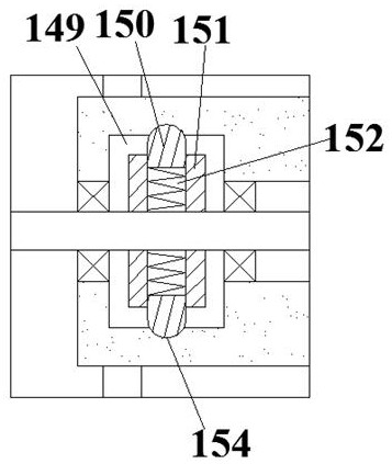
[0019] like Figure 1-5 As shown, for the convenience of description, the orientations mentioned below are stipulated as follows: the directions of up, down, left, right, front, back and figure 1 The up, down, left, right, front and back directions of the projection relationship itself are consistent. A stamping die for a round part of the present invention includes a processing block 100, and a buffer cavity 126 with an upward opening is fix...


PUM


Abstract

The invention discloses a circle rolling element stamping die comprising a processing block. A buffering cavity with an opening facing upwards is fixedly arranged in the processing block, and left-right symmetric downwards-moving inner cavities are arranged in the left and right end walls of the buffering cavity in a communicating manner. The circle rolling element stamping die is simple in structure and convenient to use; the device is provided with a buffering space, circle rolling elements which are thrown in are firstly stored in the buffering space, and stamping is carried out only when the circle rolling elements in the buffering space reach a certain number; compared with an existing stamping device, energy resources are saved; and before the device conducts the stamping step, the pulverizing step is additionally carried out, the circle rolling elements are further stamped, and the using rate of the effective space of a circle rolling element cylinder is greatly improved.

Description

technical field [0001] The invention relates to the field of processing round parts, in particular to a stamping die for round parts. Background technique [0002] Rolled round parts are commonly used workpieces. When rolled round parts are used and scrapped, they can be recycled for secondary use. When recycling, firstly, the rolled round parts need to be collected, and then punched after collection. The existing rolled round parts are stamped The device often has a rolling piece thrown into the rolling piece cylinder and the rolling piece is stamped, resulting in a waste of energy. Contents of the invention [0003] The object of the present invention is to provide a stamping die for rolled round parts, which can overcome the above-mentioned defects of the prior art. [0004] According to the present invention, a stamping die for rolled parts of the equipment of the present invention includes a processing block, and a buffer cavity with an opening facing upward is fixed...

Claims


Application Information

Patent Timeline
Patent Type & Authority Patents(China)
IPC IPC(8): B02C18/12B02C18/18B02C18/24B02C18/16B30B9/30
CPCB02C18/0084B02C18/12B02C18/16B02C18/18B02C18/24B02C2201/06B30B9/3003
Inventor 蓝茂生潘平张忠杰
Owner GOLDBELL ELECTRIC DRIVES & CONTROLS SHENZHEN CO LTD
Why Eureka
Try Eureka