A magnetic reversing locking mechanism

A locking mechanism and magnetic technology, applied in the direction of manipulators, generators/motors, electrical components, etc., can solve the problems of increasing system complexity and cost of use, and achieve high space utilization, compact volume, and eliminate heating problems Effect

Pending Publication Date: 2018-12-21
成都酷卓生命科技有限公司
View PDF0 Cites 0 Cited by
  • Summary
  • Abstract
  • Description
  • Claims
  • Application Information

AI Technical Summary

Problems solved by technology

The application of the drive control system can reduce heat generation and improve reliability to a certain extent, but it does not overcome the problem in principle, and increases the complexity and cost of the system

Method used


Image

  • A magnetic reversing locking mechanism
  • A magnetic reversing locking mechanism
  • A magnetic reversing locking mechanism

Examples


Embodiment 1

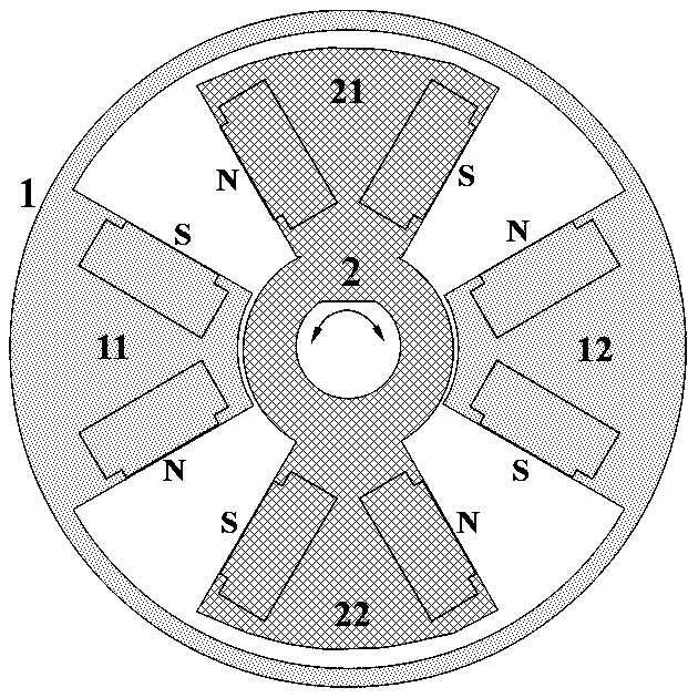
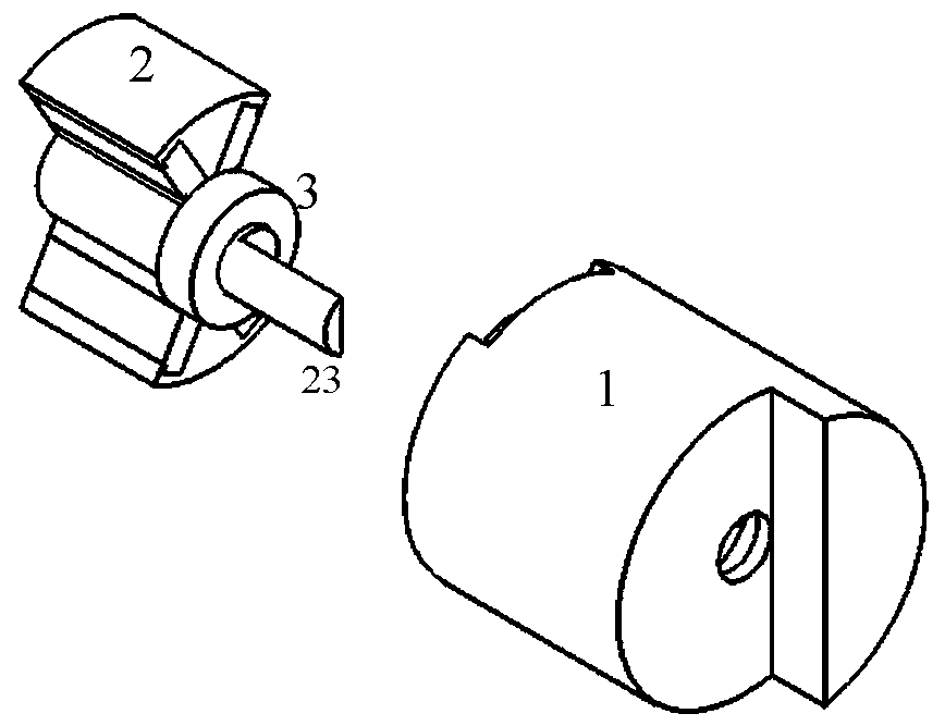
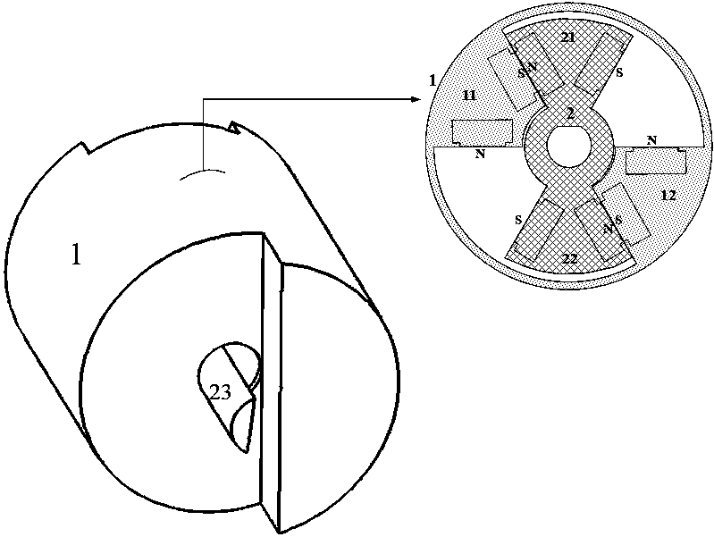
[0022] Example 1, an on-off pinch valve, see Figure 2-4 , Including the stator 1, the rotor 2 and the bearing 3; wherein the stator 1 and the rotor 2 each have two magnetic pole pairs, and the magnetic pole pairs are fan-shaped, evenly distributed along the circumference.

[0023] The on-off pinch valve includes a first state ( image 3 ) And the second state ( Figure 4 ), where the first state is the released state and the second state is the clamped state;

[0024] In the first state, the N pole in the first magnetic pole pair 21 of the rotor 2 is attached to the S pole in the first magnetic pole pair 11 of the stator 1, and the N pole in the second magnetic pole pair 22 of the rotor 2 is in contact with the stator 1 The S pole of the second magnetic pole pair 12 is attached; the attraction force between the two pairs of attaching surfaces generates a counterclockwise torque relative to the rotor shaft 23 to maintain the pinch valve in a released state.

[0025] In the second st...


PUM


Abstract

A magnetic reversing locking mechanism comprises a coaxial stator and a rotor, both of which are connected through bearings; The stator and rotor have the same number of pole pairs, and the polaritiesof any adjacent stator poles and rotor poles are opposite. The rotor can rotate around the axis of the stator to drive the magnetic pole pair of the rotor to move so that it approaches or distances from the magnetic pole pair of the stator. When the magnetic pole pair of the rotor is close to the magnetic pole pair of the stator, the attractive force between the magnetic poles forms a torque to the rotor shaft, and the torque is transmitted outwardly by the rotor shaft to realize the locking action. The magnetic pole pairs of the rotor can be fitted with the adjacent magnetic pole pairs of different stators to realize the locking action in different directions; Due to the spontaneous and persistent presence of the attractive force between the poles, the locking action can be maintained for a long time without external driving. The magnetic reversing locking mechanism of the invention has the advantages of low energy consumption and small heat generation, thus eliminating the risk of overheating failure of the traditional mechanism, and the locking force can be flexibly adjusted, and various valves and manipulator systems can be realized.

Description

Technical field [0001] The invention belongs to the field of mechanical equipment automation, and relates to a mechanism that can realize locking at multiple positions, and is particularly suitable for on-off control or gate control of a valve system, and gripping or release control of a manipulator. Background technique [0002] Valves are widely used in various fluid delivery systems to control the flow process in the pipe, including on-off control or reversing control. Especially in automated industrial systems or instruments and equipment, a large number of solenoid valves are used, which are driven by an electromagnet to move the valve core to change the valve state, and return to the position by a spring after the electromagnet is released. Take the commonly used normally closed solenoid pinch valve as an example. When the valve is powered off, the valve core is pushed by the spring to squeeze the hose to provide a certain clamping force; when the power is turned on, the va...

Claims


Application Information

Patent Timeline
Patent Type & Authority Applications(China)
IPC IPC(8): H02N11/00B25J15/02
CPCH02N11/00B25J15/02
Inventor 周晓明蒋志豪
Owner 成都酷卓生命科技有限公司
Why Eureka
Try Eureka