an eye drop bottle

A technology of eye drops bottle and bottle body, which is applied in medical containers, ophthalmic treatment, pharmaceutical packaging, etc., and can solve the problems of poor appearance and large volume of packaging bottles

Active Publication Date: 2021-01-29
SHENZHEN PEOPLES HOSPITAL
View PDF12 Cites 0 Cited by
  • Summary
  • Abstract
  • Description
  • Claims
  • Application Information

AI Technical Summary

Problems solved by technology

But the length of the piston rod of the above-mentioned scheme is equivalent to the length of the bottle body, compared with the eye drop packaging bottle of the same capacity, the overall length of the packaging bottle of this scheme is twice that of a common packaging bottle, and the volume is too large
In addition, the externally threaded piston rod for extruding eye drops is exposed outside the bottle body, making the appearance of the packaging bottle poor

Method used


Image

  • an eye drop bottle
  • an eye drop bottle
  • an eye drop bottle

Examples


Embodiment 1

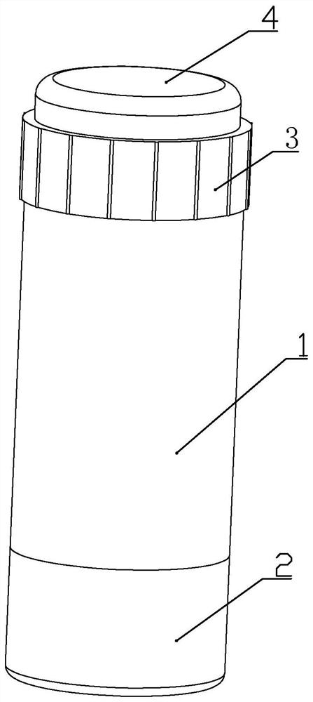
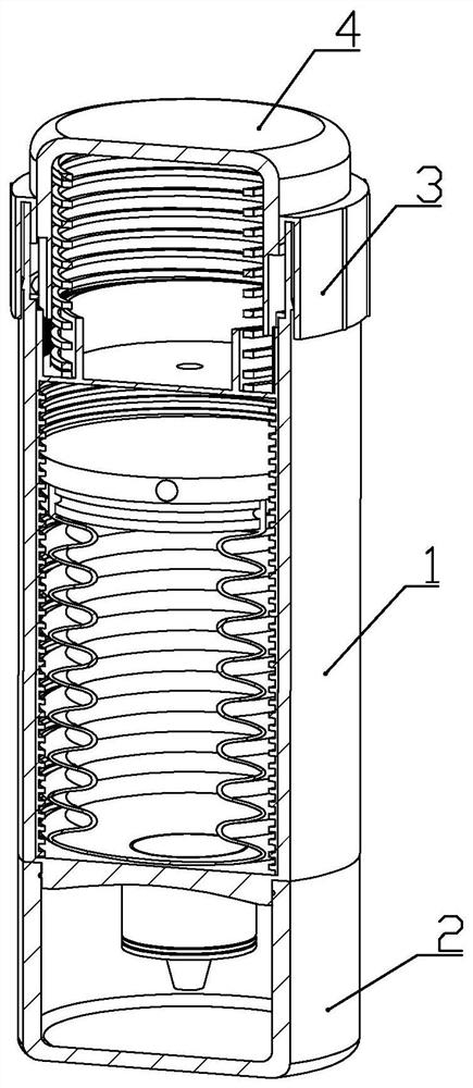
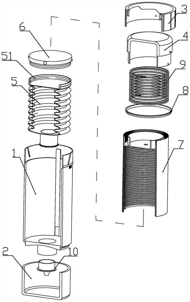
[0040] according to Figure 1 to Figure 9 As shown, the present embodiment is an eye drop bottle, which includes an outer bottle body 1 , a bottle cap 2 connected to the front end of the outer bottle body, and a drip tip 10 plugged in at the front end of the outer bottle body 1 .

[0041] A corrugated silicone liner 5 is plugged into the outer bottle body 1 , and a connecting sleeve 51 is formed on the upper end of the silicone liner 5 .

[0042] The upper end of the silicone liner 5 is connected with an inner liner extruding portion 6 , and the lower end of the inner liner extruding portion is formed with an inner liner connecting portion 61 fixedly connected with the connecting sleeve 51 .

[0043] The inner wall of the outer bottle body 1 is formed with a bar-shaped iron plate slot 121, and a bar-shaped iron plate 12 is vertically inserted in the bar-shaped iron plate slot; The permanent magnets 63 that the bar-shaped iron sheets 12 attract each other.

[0044] The outer ...

Embodiment 2

[0058] This embodiment makes the following improvements on the basis of Embodiment 1: the inner circumference of the upper end of the adjustment knob 3 is formed with a connecting ring, and the inner circumference of the connecting ring is formed with a ring inserted into the inner wall of the upper end of the outer bottle body to limit the movement of the button part 4 The retaining ring 31 of the range.

[0059] The retaining ring 31 is formed with a first step for preventing the guide protrusion from moving in the guide groove and more than one second step for adjusting the movement range of the guide protrusion along the guide groove. The first step It is equal to the length of the second step along the circumferential direction of the retaining ring.

[0060] One first step and more than one second step are distributed in a step shape along the circumferential direction of the retaining ring, and the adjacent first step, the second step, or the adjacent two second steps ...


PUM


Abstract

The invention discloses an eye drops bottle, which comprises an outer bottle body, a corrugated silicone liner is inserted into the outer bottle body, an inner liner extruding part is connected to the upper end of the silicone liner, and a sleeve socket is installed in the outer bottle body. The spiral drive sleeve outside the silicone liner, the inner wall of the spiral drive sleeve is formed with a drive internal thread; the outer wall of the extrusion part of the liner is formed with a driven protrusion that matches the drive internal thread; the upper part of the inner wall of the spiral drive sleeve is formed There are ratchets; the upper end of the outer bottle body is connected with a button part, the upper part of the outer wall of the button part is formed with a guide protrusion, the upper end of the outer bottle body is formed with an inclined guide groove slidingly matched with the guide protrusion, and the lower end of the outer wall of the button part is formed with a The ratchet cooperates with the ratchet part that drives the rotation of the helical drive sleeve; the effective space utilization rate of the present invention is high, and only part of the button part for manual operation is exposed on the top of the outer bottle body, so that the overall appearance of the packaging bottle is more regular and beautiful.

Description

technical field [0001] The invention belongs to the field of medicine packaging bottles, in particular to an eye drop packaging bottle. Background technique [0002] The Chinese patent whose document number is CN105691937A discloses a kind of eye drop packaging bottle, which comprises a cylindrical bottle body. The front end of the bottle body is formed with a drip tube. There is a piston assembly; the piston assembly includes a piston body and a piston rod; the outer wall of the piston rod is formed with external threads, and the bottle body nut part; the nut part is formed with internal threads; the nut part includes a socket ring, and the outer edge; the outer wall of the insertion ring is formed with a chuck, and the side wall of the bottle body is formed with a bayonet; the piston rod is formed with a strip bayonet, and a dial is worn inside the strip bayonet Rod; the strip-shaped bayonet is formed with bayonet teeth; the driving rod includes a driving rod body, a posi...

Claims


Application Information

Patent Timeline
Patent Type & Authority Patents(China)
IPC IPC(8): A61J1/05A61J1/14A61F9/00
CPCA61F9/0008A61J1/05A61J1/14
Inventor 李华谢宁李伟聂爱芹黄文佳
Owner SHENZHEN PEOPLES HOSPITAL
Why Eureka
Try Eureka