Wallboard installation robot
A technology of robots and wall panels, applied in the field of construction robots, can solve the problems of inconvenient installation, high risk for workers, and difficulty in manual operation, and achieve the effects of high work efficiency and strong practicability
Active Publication Date: 2019-09-03
GUANGDONG BOZHILIN ROBOT CO LTD
8 Cites 17 Cited by
AI-Extracted Technical Summary
Problems solved by technology
[0002] With the continuous development of the construction industry, robots that help construction operations are more and more popular in the construction industry. At present, in some buildings, s...
View moreMethod used
According to some embodiments of the present invention, in conjunction with Fig. 1, support frame 1 is located at one end of chassis 810 (such as the front end of chassis 810), and support frame 1 and chassis 810 can be connected by pin shaft, and wallboard support body 2 The bottom is provided with wallboard 2000 bracket fork 23. For example, the supporting fork 23 of the wallboard 2000 can include two, and the supporting fork 23 of the two wallboard 2000 can be arranged at intervals along the left and right direction, and the supporting fork 23 of the wallboard 2000 is detachably connected with the wallboard support The fork 23 is easy to support and transfer the wall panel 2000 .
For example, a lifting slide rail 11 can be formed on the support frame 1, and the lifting slide rail 11 can extend along the up and down direction, and the rear side of the translation base plate 3 can be formed with a lifting slide block 31, and the lifting slide block 31 and the lifting slide rail 11 Matching, thus, through the cooperation of the lifting slider 31 and the lifting slide rail 11, the translation base plate 3 can slide relative to the support frame 1 in the up and down direction, so as to facilitate the adjustment of the position of the wall panel 2000 in the up and down direction.
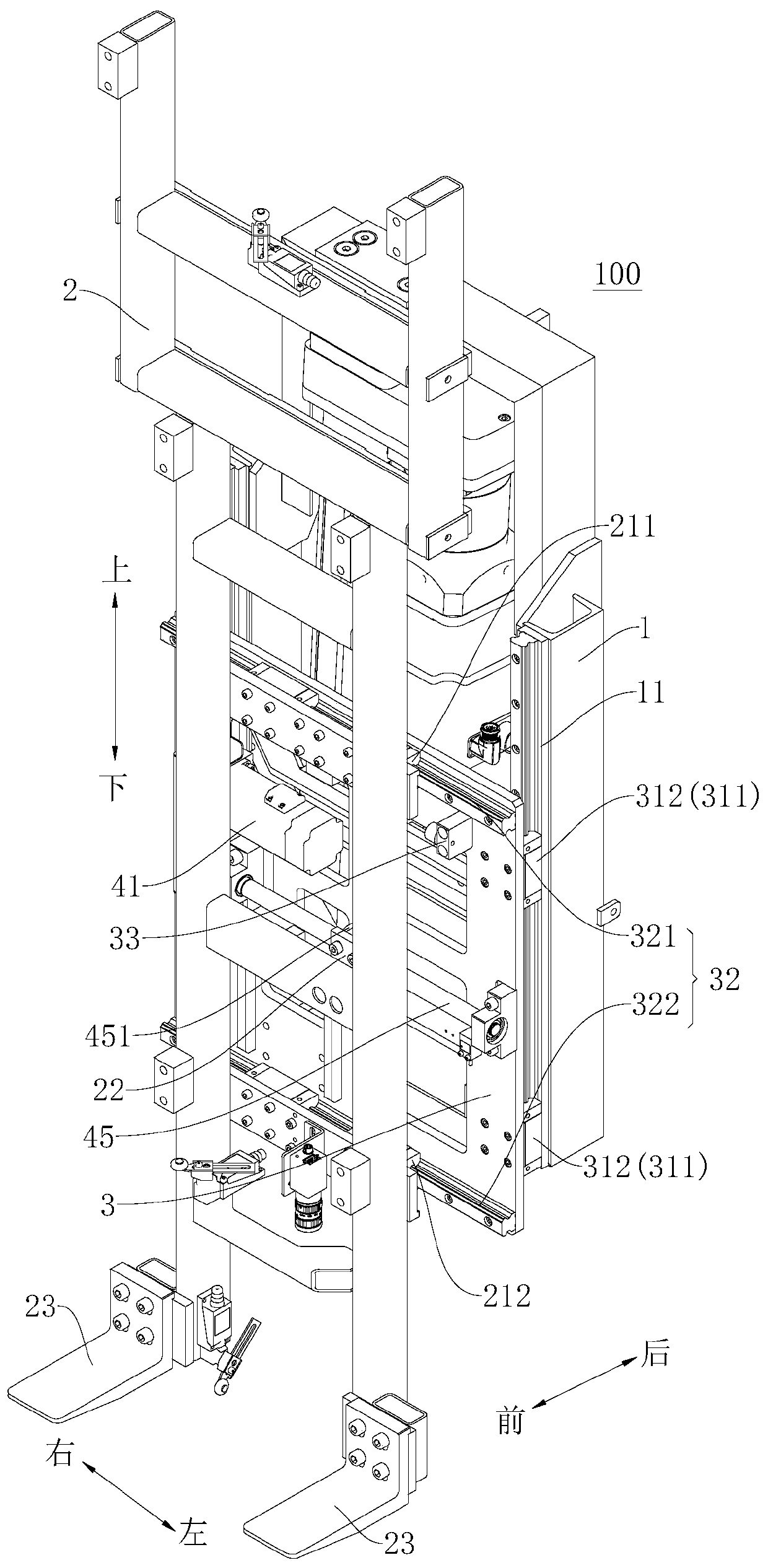
For example, in the front-rear direction shown in Figure 3, the front side of the translation base plate 3 can be provided with a translation slide rail 32, and the translation slide rail 32 can extend along the left-right direction, and the wallboard support body 2 is provided with a translation slide block 21. The translation slider 21 is matched with the translation slide rail 32. Thus, through the cooperation of the translation slider 21 and the translation slide rail 32 , the horizontal translation of the wall panel support body 2 relative to the translation base plate 3 can be realized, which is convenient for adjusting the position of the wall panel 2000 in the horizontal direction.
It should be further explained that the two jaw devices 500 can act synchronously to form an encircling posture, and when used to grab the wallboard 2000, clamp the left and right sides of the wallboard 2000, the two jaw devices 500 They can also act independently, that is, one of the two clamping jaw devices 500 clamps one side of the wall panel 2000, the other of the two clamping jaw devices 500 has the clamping jaw mechanism 530 stored, and the sliding plate 520 slides to the second position to avoid interference when the wall panel 2000 is installed.
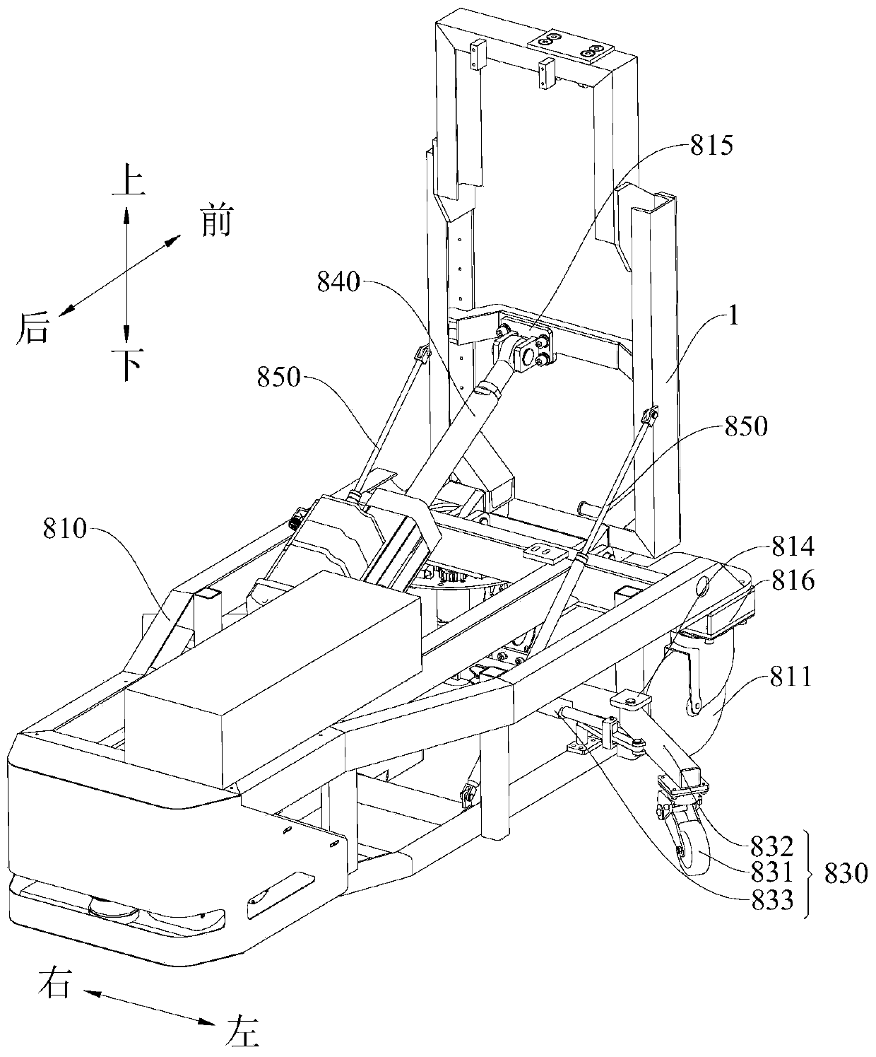
Optionally, as shown in Figures 1 and 2, the wallboard 2000 transportation robot 800 also includes a buffer spring 850, and the buffer spring 850 is telescopically located between the chassis 810 and the support frame 820, when the electric push rod drives When the support frame 820 is active, the buffer spring 850 can buffer the force applied to the support frame 820 by the electric push rod, so that the support frame 820 can rotate slowly, which not only helps the movement of the support frame 820 and the wallboard 2000 to be relatively stable, but also makes the support frame 820 The wallboard 2000 can be better clamped, the wallboard 2000 is not easy to fall off, and the torque will not rise suddenly, thereby protecting the second electric cylinder. Furthermore, the buffer spring 850 can also limit the relative position between the chassis 810 and the support frame 820 , so that the support frame 820 remains stationary after moving to a certain position, thereby facilitating the relative stability of the support frame 820 and the wall panel 2000 .
Optionally, referring to Fig. 3 and Fig. 6, a screw slider 451 can be provided on the translational ball screw 45, and a connecting block 22 matched with the screw slider 451 is provided on the wallboard support body 2, The screw slider 451 cooperates with the connecting block 22 to connect the translational ball screw 45 with the wallboard support 2 . Thus, through the cooperation of the screw slider 451 and the connecting block 22, it is easy to realize the assembly connection between the translational ball screw 45 and the wallboard support body 2, and it is convenient to drive the wallboard support body 2 to translate by the translational ball screw 45. The adjustment of the position of the wall panel 2000 in the horizontal direction is realized.
Specifically, the first translation slide rail 321 can be located at the upper end of the translation base plate 3; the second translation slide rail 322 can be located at the lower end of the translation base plate 3, and the translation ball screw 45 can be located at the first translation slide rail 321 and the second translation slide rail 322. For example, the translation ball screw 45 may extend along the left-right direction shown in FIG. 4 , and the translation ball screw 45 may be located in the middle of the translation bottom plate 3 along the up-down direction. Therefore, by arranging the translation ball screw 45 between the first translation slide rail 321 and the second translation slide rail 322 , it is beneficial to ensure the smooth movement of the wall panel support body 2 .
The clamping device 1000 is located on the wallboard support 2 and is used for clamping and releasing the wallboard 2000, that is to say, the clamping device 1000 is mounted on the wallboard support 2, and is passed through the wallboard support Installing the clamping device 1000 on 2 can facilitate the wall panel installation robot 10000 to grab or release the wall panel 2000. Further, the clamping device 1000 has at least a clamping position and a release position. When the clamping device 1000 is in the clamping position, the clamping device 1000 can grab the wall panel 2000 to transport the wall panel 2000 by the wall panel installation robot 10000, When the clamping device 1000 is at the release position, the clamping device 1000 can release the grasped wall panel 2000, thereby completing the transportation or installation of the wall panel installation robot 10000, which has high reliability and strong practicability.
The second translation slide block 212 is matched with the second translation slide rail 322, the second translation slide block 212 includes one or more, when the second translation slide block 212 includes a plurality, a plurality of second translation slide blocks 212 are arranged at intervals in the left and right direction of the translation base plate 3 . Thus, through the cooperation of the second translation slide rail 322 and the second translation slider 212 , the translation of the wall panel 2000 is easily realized, and the adjustment of the position of the wall panel 2000 in the horizontal direction is facilitated.
The third electric cylinder is located between the base 610 and the chassis 1 to control the lifting of the wooden wedge device 600, thus, by setting the third electric cylinder on the wooden wedge device 600, the wooden wedge device can be pushed 600 When the wooden wedge 700 is pushed out, the wooden wedge device 600 can adjust the relative height between the wooden wedge 700 and the chassis 1, so that the wooden wedge device 600 can more easily place the wooden wedge 700 between the wallboard 2000 and the ground in the gap.
Thus, according to the wallboard installation robot 10000 of the implementation of the present invention, by setting the clamping device 1000 on the wallboard support body 2, the wallboard installation robot 10000 can grab the wallboard 2000, and the clamping device 1000 can grab the wallboard 2000. After the wall panel 2000 is taken, the translation jacking mechanism 100 can drive the wall panel 2000 to translate in the up and down directions and left and right directions of the wall panel installation robot 10000, and can adjust the position of the wall panel 2000 on the wall panel installation robot 10000, thereby facilitating The wall panel installation robot 10000 carries or installs the wall panel 2000. After the wall panel installation robot 10000 transports or installs the wall panel 2000 to a corresponding position, the clamping device 1000 can release the wall panel 2000 to complete the wall panel 2000. Handling or installation, high work efficiency, strong practicability.
[0082] In some examples, the first to third traveling wheels can be installed on the chassis 810 through the mounting seat 816, and a limit mechanism is provided on the mounting seat 816. When the traveling direction of the first to the third traveling wheels is in the In the front-rear direction or left-right direction, the limit mechanism can limit the walking direction of the first to third traveling wheels to a certain extent, so that the first to third traveling wheels remain in the front-rear direction or left-right direction, which is beneficial to the wall panel installation robot 10000 walking, good stability. When it is necessary to change the walking direction of the first to third traveling wheels, the first to third traveling wheels can be driven by a certain force, so that the first to third traveling wheels are out of the limit of the limit mechanism, so that the wallboard can be changed Install the walking direction of the robot 10000.
[0084] According to the wall panel installation robot 10000 of the embodiment of the present invention, the first traveling wheel 811 and the third traveling wheel 813 are arranged side by side in the left-right direction, and the second traveling wheel is located between the first traveling wheel 811 and the third traveling wheel in the left-right direction. Between the traveling wheels 813, and the second traveling wheel is located at the rear side of the first traveling wheel 811 and the third traveling wheel 813, as shown in Figure 1 and Figure 2, the first traveling wheel 811 and the third traveling wheel 813 are adjacent to the chassis 810 and the first traveling wheel 811 and the third traveling wheel 813 are respectively adjacent to the left and right sides of the chassis 810, the second traveling wheel is adjacent to the rear side of the chassis 810, and the second traveling wheel is located at the first traveling wheel in the left and right direction. 811 and the third traveling wheel 813, thus, by setting the first traveling wheel 811, the second traveling wheel and the third traveling wheel 813 adjacent to the three corners of the chassis 810, the wall panel installation robot 10000 Has good stability.
[0085] According to the wall panel installation robot 10000 according to the embodiment of the present invention, the wall panel installation robot 10000 also includes an auxiliary wheel mechanism 830, the auxiliary wheel mechanism 830 includes an auxiliary wheel 831, and the auxiliary wheel 831 is movable between an unfolded position and a retracted position Ground is located on the chassis 810, when the auxiliary wheels 831 are in the unfolded position, the auxiliary wheels 831 are located at the outside of the chassis 810, and when the auxiliary wheels 831 are at the retracted position, the auxiliary wheels 831 are located at the underside of the chassis 810. That is to say, the auxiliary wheel 831 has a deployed position and a retracted position. When the auxiliary wheel 831 is in the deployed position, the auxiliary wheel 831 is located on the outside of the chassis 810. The outside here refers to the projection of the auxiliary wheel 831 on the horizontal plane of the chassis 810. Therefore, the auxiliary wheel 831 can share the walking pressure of the first traveling wheel 811, the second traveling wheel and the third traveling wheel 813, and the auxiliary wheel 831 can support the wall panel installation robot 10000 on the outside of the wall panel installation robot 10000 , can effectively prevent the wall panel installation robot 10000 from overturning, and can make the wall panel installation robot 10000 more stable when walking. Avoid increasing the occupied area of the wall panel installation robot 10000 after adding the auxiliary wheel mechanism 830 on the wall panel installation robot 10000 .
[0086] Optionally, the auxiliary wheel mechanism 830 further includes a connecting rod 832, and the auxiliary wheel 831 is pivotably arranged on the chassis 810 through the connecting rod 832, thus, through the connecting rod 832, the auxiliary wheel 831 can be in the unfolded position When the distance between the auxiliary wheels 831 and the chassis 810 is increased, the auxiliary support effect of the auxiliary wheels 831 on the wall panel installation robot 10000 can be further improved, so that the balance of the wall panel installation robot 10000 is better. The chassis 810 is provided with a first fixing part 814, and the connecting rod 832 can be connected to the first fixing part 814 through a pin shaft, thus, the disassembly and assembly of the connecting rod 832 and the first fixing part 814 can be facilitated, so that the wall panel can be improved. Assembly efficiency of 10,000 installation robots.
[0087] Optionally, the auxiliary wheel mechanism 830 further includes an auxiliary wheel driving device 833, and the auxiliary wheel driving device 833 can drive the auxiliary wheel 831 to move between the deployed position and the retracted position. Therefore, driving the auxiliary wheel 831 through the auxiliary wheel driving device 833 can save manpower, so that the auxiliary wheel 831 runs between the unfolded position and the retracted position, with high movement efficiency and good movement precision.
[0088] Optionally, the auxiliary wheel driving device 833 includes a first electric cylinder, and the first electric cylinder includes a retractable first electric push rod, and the first electric push rod is connected with the connecting rod 832, that is to say, the first electric push rod The push rod can cooperate with the connecting rod 832 and push the connecting rod 832 to move, so that the connecting rod 832 drives the auxiliary wheel 831 to move between the deployed position and the retracted position. Further, the first electric push rod can drive the connecting rod 832, so that after the auxiliary wheel 831 moves to the unfolded position or the retracted position, the movement of the auxiliary wheel 831 can also be restricted, so that the auxiliary wheel 831 remains in the deployed position or the retracted position. High, stro...
View moreAbstract
The invention discloses a wallboard installation robot. The wallboard installation robot comprises a chassis, a supporting frame, a horizontal movement jacking mechanism and a clamping device. The supporting frame is arranged on the chassis in the manner that the supporting frame can pivot. The horizontal movement jacking mechanism is arranged on the supporting frame. The horizontal movement jacking mechanism comprises a wallboard supporting body and a horizontal movement bottom plate. The wallboard supporting body is connected with the supporting frame and is used for supporting a wallboard.The horizontal movement bottom plate is arranged between the supporting frame and the wallboard supporting body. The horizontal movement bottom plate can slide in the vertical direction relative to the supporting frame. The wallboard supporting body can slide in the horizontal direction relative to the horizontal movement bottom plate. The clamping device is arranged on the wallboard supporting body and is used for clamping and releasing the wallboard. The wallboard installation robot of the embodiment of the invention is high in work efficiency.
Application Domain
Technology Topic
Image
Examples
- Experimental program(1)
Example Embodiment
[0069] The embodiments of the present invention are described in detail below. Examples of the embodiments are shown in the accompanying drawings, in which the same or similar reference numerals indicate the same or similar elements or elements with the same or similar functions. The embodiments described below with reference to the drawings are exemplary, and are only used to explain the present invention, but should not be understood as limiting the present invention.
[0070] In the description of the present invention, it should be understood that the terms "center", "longitudinal", "transverse", "length", "width", "thickness", "upper", "lower", "front", " "Back", "Left", "Right", "Vertical", "Horizontal", "Top", "Bottom", "Inner", "Outer", "Clockwise", "Counterclockwise", "Axial", The orientation or positional relationship indicated by "radial", "circumferential", etc. is based on the orientation or positional relationship shown in the drawings, and is only for the convenience of describing the present invention and simplifying the description, rather than indicating or implying the pointed device or element It must have a specific orientation, be constructed and operated in a specific orientation, and therefore cannot be understood as a limitation to the present invention. In addition, the features defined with "first" and "second" may explicitly or implicitly include one or more of these features. In the description of the present invention, unless otherwise specified, "plurality" means two or more.
[0071] In the description of the present invention, it should be noted that the terms "installation", "connected" and "connected" should be understood in a broad sense, unless otherwise clearly specified and limited. For example, they can be fixed or detachable. Connected or integrally connected; it can be a mechanical connection or an electrical connection; it can be directly connected or indirectly connected through an intermediate medium, and it can be the internal communication between two components. For those of ordinary skill in the art, the specific meaning of the above-mentioned terms in the present invention can be understood in specific situations.
[0072] Reference below Figure 1-Figure 23 The wall panel installation robot 10000 according to the embodiment of the present invention is described.
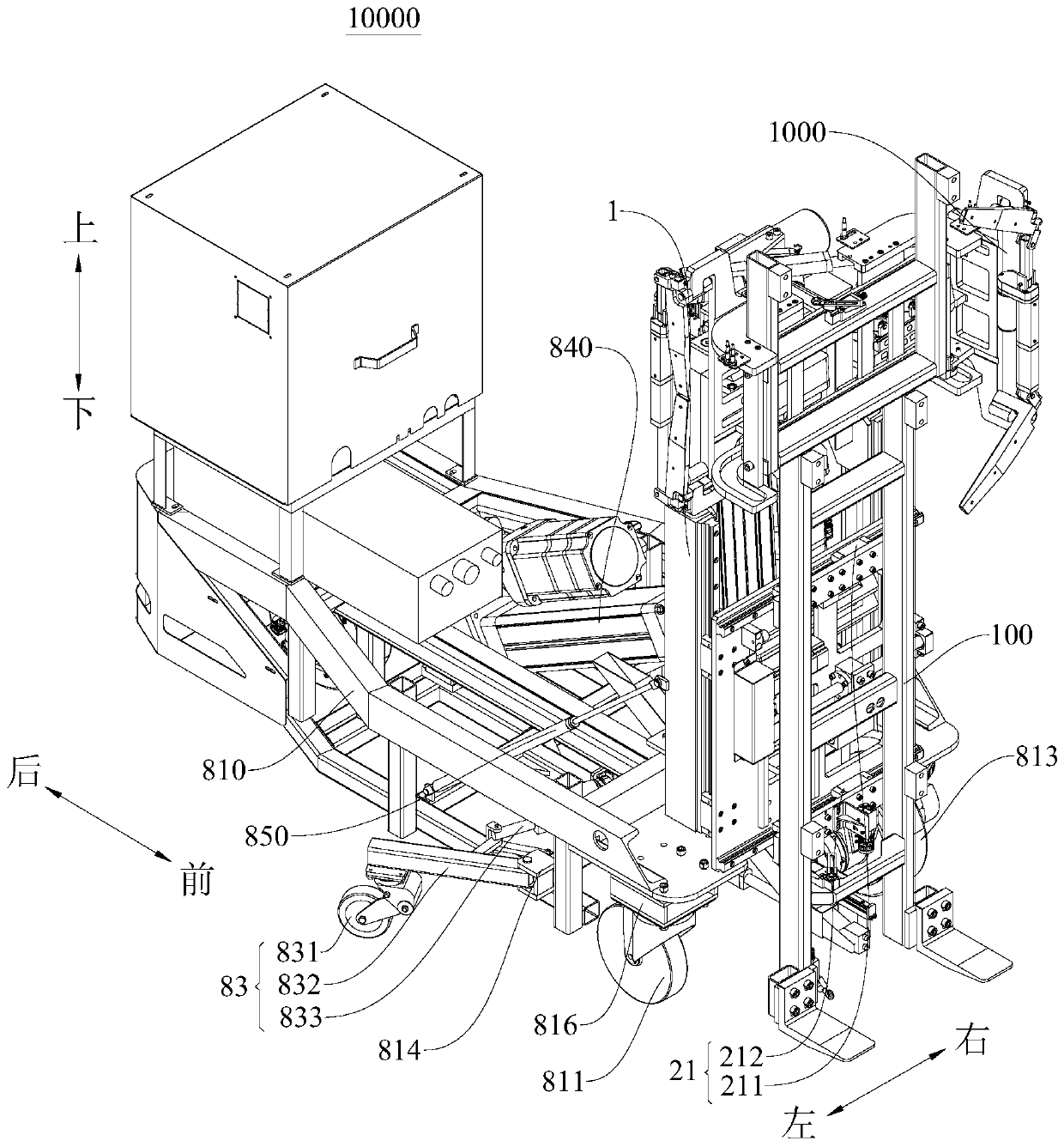
[0073] Such as figure 1 with figure 2 As shown, the wall panel installation robot 10000 according to the embodiment of the present invention includes a chassis 810, a support frame 1, a translational lifting mechanism 100 and a clamping device 1000. The clamping device 1000 can grab the wall panel 2000 (the wall panel 2000 can refer to Figure 15 (Shown), after the clamping device 1000 grabs the wall panel 2000, the translational lifting mechanism 100 can adjust the position of the wall panel 2000 on the wall panel installation robot 10000 to facilitate the installation or transportation of the wall panel 2000.
[0074] Specifically, the support frame 1 is pivotally disposed on the chassis 810, that is, the support frame 1 is installed on the chassis 810, and the support frame 1 can rotate relative to the chassis 810 after being installed on the chassis 810. E.g figure 1 As shown, the clamping device 1000 grabs the wall panel 2000 (the wall panel 2000 can refer to Figure 15 After shown), the wall panel 2000 can be located on one side of the support frame 1, and the support frame 1 can rotate to a certain extent relative to the chassis 810 toward the other side of the support frame 1, so that the wall panel 2000 can be more firmly leaned on the support Therefore, it can reduce the pressure of the clamping device 1000 to grab the wall panel 2000, protect the clamping device 1000, facilitate the handling of the wall panel 2000 by the wall panel installation robot 10000, and improve the handling efficiency of the wall panel 2000.
[0075] The support frame 1 is provided with a translational lifting mechanism 100. The translational lifting mechanism 100 can be used for the wall panel installation robot 10000 to translate and/or lift the wall panel 2000. The translational lifting mechanism 100 can include the wall panel support 2 and translate The base plate 3, the wall plate support body 2 is connected to the support frame 1, the wall plate support body 2 can be used to support the wall plate 2000, the translation base plate 3 is arranged between the support frame 1 and the wall plate support body 2, and the translation base plate 3 is relative to the support The frame 1 is slidable in the up and down direction, and the wall board support 2 is slidable in the horizontal direction relative to the translational bottom plate 3.
[0076] For example, in figure 1 In the front-rear direction shown in the figure, the translational bottom plate 3 can be provided on the front side of the support frame 1, and the wall panel support 2 can be provided on the front side of the translational bottom plate 3, and the translational bottom plate 3 is configured to move up and down relative to the support frame 1. It is slidable, and the wall panel support 2 is configured to be slidable in the left-right direction relative to the translational bottom plate 3. In this way, it is convenient to adjust the position of the wall panel 2000 in the horizontal direction and the vertical direction.
[0077] The clamping device 1000 is arranged on the wall panel support 2 and is used to clamp and release the wall panel 2000, that is, the clamping device 1000 is installed on the wall panel support 2 in cooperation, by installing on the wall panel support 2 The clamping device 1000 can facilitate the wall panel installation robot 10000 to grab or release the wall panel 2000. Further, the clamping device 1000 has at least a clamping position and a release position. When the clamping device 1000 is in the clamping position, the clamping device 1000 can grab the wall panel 2000 to transport the wall panel 2000 by the wall panel installation robot 10000, When the clamping device 1000 is in the release position, the clamping device 1000 can release the grabbed wall panel 2000, thereby completing the transportation or installation of the wall panel installation robot 10000, which has high reliability and strong practicability.
[0078] Therefore, the wall panel installation robot 10000 according to the implementation of the present invention can make the wall panel installation robot 10000 grab the wall panel 2000 and the clamping device 1000 grab the wall panel by setting the clamping device 1000 on the wall panel support 2 After 2000, the translation jacking mechanism 100 can drive the wall panel 2000 to move in the up and down and left and right directions of the wall panel installation robot 10000, and can adjust the position of the wall panel 2000 on the wall panel installation robot 10000, thereby facilitating wall panel installation The robot 10000 transports or installs the wall panel 2000. After the wall panel installation robot 10000 transports or installs the wall panel 2000 to the corresponding position, the clamping device 1000 can release the wall panel 2000 to complete the transport or installation of the wall panel 2000 , High work efficiency and strong practicability.
[0079] In some embodiments of the present invention, the chassis 810 is provided with first to third travel wheels, that is, the chassis 810 is provided with a first travel wheel 811, a second travel wheel (not shown in the figure), and a first travel wheel. With three traveling wheels 813, by arranging the first traveling wheel 811, the second traveling wheel and the third traveling wheel 813 on the chassis 810, the wall panel installation robot 10000 can be made to walk. Compared with the four-wheel walking mechanism of the handling robot in the related art, the wall panel installation robot 10000 of the embodiment of the present invention can walk through three traveling wheels, which reduces the installation of one traveling wheel and can improve the installation efficiency of the wall panel installation robot 10000 , The area of the chassis 810 can also be reduced, thereby helping to reduce the volume of the wall panel installation robot 10000.
[0080] Further, the first traveling wheel 811 and the second traveling wheel are spaced apart in the front-rear direction of the chassis 810, specifically, for example figure 1 with figure 2 As shown, in the front-rear direction, the first traveling wheel 811 is disposed close to the front end of the chassis 810, and the second traveling wheel is disposed close to the rear end of the chassis 810. The first traveling wheel 811 and the second traveling wheel are spaced apart in the front-rear direction. distance.
[0081] The first traveling wheels 811 to the third traveling wheels 813 are each configured to be able to travel in at least two directions perpendicular to each other. E.g figure 1 with figure 2 As shown, when wall panel installation robot 10000 needs to be in figure 1 When moving in the front and rear or left and right directions shown, the walking directions of the first traveling wheel 811, the second traveling wheel, and the third traveling wheel 813 can be changed between the front-rear direction and the left-right direction, so that the wall panel installation robot 10000 It can move in the front and back or left and right directions. Compared with the forklift chassis 810 in the related art, only the rear wheels can be rotated, and the front two wheels can only move forward and backward, and cannot realize forward and backward translation. The three traveling wheels of the wall panel installation robot 10000 in the embodiment of the present invention are in the forward and backward directions and It can walk in the left and right directions, so that the wallboard installation robot 10000 of the embodiment of the present invention has better flexibility, and is also conducive to the wallboard installation robot 10000 walking in some relatively small areas, with high reliability and practicability. Strong.
[0082] In some examples, the first to third traveling wheels can be mounted on the chassis 810 through the mounting seat 816, and a limit mechanism is provided on the mounting seat 816. When the traveling direction of the first to third traveling wheels is in the front-rear direction or In the left and right direction, the limit mechanism can restrict the walking direction of the first to third traveling wheels to a certain extent, so that the first to third traveling wheels are kept in the front-rear direction or the left-right direction, thereby facilitating the walking of the wall panel installation robot 10000 , Good stability. When it is necessary to change the walking direction of the first to third traveling wheels, the first to third traveling wheels can be driven by a certain force, so that the first to third traveling wheels are out of the limit of the limit mechanism, so that the wall panel can be changed Install the walking direction of the robot 10000.
[0083] According to the wall panel installation robot 10000 of the embodiment of the present invention, the first traveling wheel 811 and the second traveling wheel have the same structure and are configured to be able to travel in two directions perpendicular to each other, and the third traveling wheel 813 is a universal wheel. Thus, the walking direction of the third traveling wheel 813 can be changed relatively easily. By changing the traveling direction of the third traveling wheel 813, the first traveling wheel 811 and the second traveling wheel can be guided to change the traveling direction, thereby changing the wall panel installation robot The walking direction of 10000 has simple structure and convenient operation. At the same time, the structure of the first traveling wheel 811 and the second traveling wheel are the same, which can reduce the production cost of the first traveling wheel 811 and the second traveling wheel. Of course, it is understandable that the first traveling wheel 811, the second traveling wheel, and the third traveling wheel 813 may all be universal wheels, or one of the first traveling wheel 811, the second traveling wheel and the third traveling wheel 813 Any one is a universal wheel, there is no restriction here.
[0084] According to the wall panel installation robot 10000 of the embodiment of the present invention, the first traveling wheel 811 and the third traveling wheel 813 are arranged side by side in the left-right direction, and the second traveling wheel is located at the first traveling wheel 811 and the third traveling wheel 813 in the left-right direction. Between, and the second traveling wheel is located behind the first traveling wheel 811 and the third traveling wheel 813, such as figure 1 with figure 2 As shown, the first traveling wheel 811 and the third traveling wheel 813 are adjacent to the front side of the chassis 810, and the first traveling wheel 811 and the third traveling wheel 813 are respectively adjacent to the left and right sides of the chassis 810, and the second traveling wheel is adjacent to the chassis 810. The second traveling wheel is located between the first traveling wheel 811 and the third traveling wheel 813 in the left-right direction. Therefore, the first traveling wheel 811, the second traveling wheel and the third traveling wheel 813 are adjacent to the chassis The location of the three corners of the 810 can make the wall panel installation robot 10000 have better stability.
[0085] According to the wall panel installation robot 10000 according to the embodiment of the present invention, the wall panel installation robot 10000 further includes an auxiliary wheel mechanism 830. The auxiliary wheel mechanism 830 includes an auxiliary wheel 831. The auxiliary wheel 831 can be movably arranged between the deployed position and the retracted position. On the chassis 810, when the auxiliary wheel 831 is in the extended position, the auxiliary wheel 831 is located outside the chassis 810, and when the auxiliary wheel 831 is in the retracted position, the auxiliary wheel 831 is located on the lower side of the chassis 810. In other words, the auxiliary wheel 831 has an expanded position and a retracted position. When the auxiliary wheel 831 is in the expanded position, the auxiliary wheel 831 is located on the outside of the chassis 810. The outside here refers to the projection of the auxiliary wheel 831 on the horizontal plane of the chassis 810. As a result, the auxiliary wheel 831 can share the walking pressure of the first traveling wheel 811, the second traveling wheel and the third traveling wheel 813, and the auxiliary wheel 831 can support the wall panel mounting robot 10000 outside the wall panel mounting robot 10000 , Can effectively prevent the wall panel installation robot 10000 from overturning, and can make the wall panel installation robot 10000 more stable and stable when walking. When the auxiliary wheel 831 is in the retracted position, the auxiliary wheel 831 is located on the lower side of the chassis 810, thus, It is avoided that the auxiliary wheel mechanism 830 is added to the wall panel installation robot 10000 to increase the floor area of the wall panel installation robot 10000.
[0086] Optionally, the auxiliary wheel mechanism 830 further includes a connecting rod 832, and the auxiliary wheel 831 is pivotally disposed on the chassis 810 through the connecting rod 832. Therefore, the auxiliary wheel 831 can be increased when the auxiliary wheel 831 is in the unfolded position through the connecting rod 832. The distance between the large auxiliary wheel 831 and the chassis 810 can further improve the auxiliary support effect of the auxiliary wheel 831 on the wall panel installation robot 10000, thereby making the wall panel installation robot 10000 more balanced. The chassis 810 is provided with a first fixing portion 814, and the connecting rod 832 can be connected to the first fixing portion 814 by a pin shaft, thereby facilitating the disassembly and assembly of the connecting rod 832 and the first fixing portion 814, thereby improving the wall panel The assembly efficiency of the installation robot 10000.
[0087] Optionally, the auxiliary wheel mechanism 830 further includes an auxiliary wheel driving device 833, which can drive the auxiliary wheel 831 to move between the deployed position and the retracted position. Therefore, the auxiliary wheel 831 is driven by the auxiliary wheel driving device 833, which can save manpower, so that the auxiliary wheel 831 runs between the deployed position and the retracted position, with high movement efficiency and good movement accuracy.
[0088] Optionally, the auxiliary wheel drive device 833 includes a first electric cylinder, and the first electric cylinder includes a retractable first electric push rod, and the first electric push rod is connected to the connecting rod 832, that is, the first electric push rod can It cooperates with the connecting rod 832 and pushes the connecting rod 832 to move, so that the connecting rod 832 drives the auxiliary wheel 831 to move between the deployed position and the retracted position. Further, the first electric push rod can drive the connecting rod 832, so that after the auxiliary wheel 831 moves to the extended position or the retracted position, the movement of the auxiliary wheel 831 can be restricted, so that the auxiliary wheel 831 can be maintained in the extended position or the retracted position. High and stable. Further, the connection point between the first electric push rod and the connecting rod 832 is located outside the first fixing part 814, where the outside refers to the outside of the projection of the connection point on the horizontal plane of the chassis 810, specifically, for example, figure 1 As shown, the left side of the chassis 810 has a first fixing portion 814, and the left side of the first fixing portion 814 extends outside the chassis 810, thereby reducing the difficulty of assembly between the first fixing portion 814 and the connecting rod 832. Thereby, the assembly efficiency between the first fixing portion 814 and the connecting rod 832 is improved.
[0089] According to the wall panel installation robot 10000 according to the embodiment of the present invention, the auxiliary wheel mechanism 830 includes two and is respectively provided on the left and right sides of the chassis 810. Therefore, auxiliary wheel mechanisms 830 are provided on the left and right sides of the chassis 810, which can support the wall panel installation robot 10000 on the left and right sides of the chassis 810, so that the wall panel installation robot 10000 has better stability.
[0090] According to the wall panel installation robot 10000 according to the embodiment of the present invention, the chassis 810 is provided with two second fixing parts 815 spaced apart left and right, and the support frame 1 is respectively connected to the two second fixing parts 815 via pins. Therefore, through the cooperation of the shaft pin and the second fixing portion 815, the disassembly and assembly between the chassis 810 and the support frame 1 can be facilitated, and the disassembly and assembly efficiency is high. At the same time, after the axle pin is matched with the second fixing part 815, the support frame 1 can rotate relative to the chassis 810. Therefore, the two second fixing parts 815 can be matched with the axle pin to make the support frame 1 rotate relative to the chassis 810. It has good balance and stability. Of course, it is understandable that the chassis 810 may also be provided with multiple second fixing parts 815, and the chassis 810 can be better connected to the support frame 1 through the multiple second fixing parts 815, so that the support frame 1 is relative to the chassis The 810 is more reliable when it rotates relatively.
[0091] Optionally, the wall panel installation robot 10000 further includes a supporting frame 1 driving device 840, which is provided on the chassis 810 and connected to the supporting frame 1 to drive the supporting frame 1 to pivot relative to the chassis 810. E.g figure 1 with figure 2 As shown, one end of the support frame 1 driving device 840 can be connected to the chassis 810, and the other end is connected to the support frame 1. The support frame 1 driving device 840 can drive the support frame 1 to rotate relative to the chassis 810, which can save manpower and improve work efficiency. At the same time, the accuracy when the support frame 1 rotates can be improved.
[0092] Optionally, the driving device 840 of the support frame 1 includes a second electric cylinder, the second electric cylinder includes a telescopic second electric push rod, the second electric push rod is connected to the support frame 1 and the second electric push rod is connected to the support frame 1 The connection point is located above the second fixing portion 815. Thus, the second electric cylinder can drive the second electric push rod, so that the second electric push rod drives the support frame 1 to rotate with the second fixed portion 815 as the rotation axis. Further, after the second electric cylinder and the second electric push rod cooperate to drive the support frame 1 to rotate, the second electric cylinder and the second electric push rod can also restrict the movement of the support frame 1, so that the support frame 1 can remain stationary. It is advantageous for the support frame 1 to stably clamp the wallboard 2000, thereby facilitating the wallboard installation robot 10000 to carry the wallboard 2000 better.
[0093] Optionally, such as figure 1 with figure 2 As shown, the wallboard 2000 transportation robot 800 further includes a buffer spring 850, which is telescopically arranged between the chassis 810 and the support frame 820. When the electric push rod drives the support frame 820 to move, the buffer spring 850 can buffer the electric push The force exerted by the rod on the support frame 820 enables the support frame 820 to rotate slowly, which not only facilitates the movement of the support frame 820 and the wall panel 2000 to be relatively stable, so that the support frame 820 can better clamp the wall panel 2000, the wall panel 2000 It is not easy to fall off, and the torque will not rise suddenly, thereby protecting the second electric cylinder. Further, the buffer spring 850 can also limit the relative position between the chassis 810 and the support frame 820, so that the support frame 820 remains stationary after moving to a certain position, thereby facilitating the relative stability of the support frame 820 and the wall panel 2000.
[0094] Optionally, such as figure 1 with figure 2 As shown, the buffer spring 850 includes two and is respectively arranged on the left and right sides of the support frame driving device 840. In other words, there are two buffer springs 850, and the two buffer springs 850 can further buffer the force applied to the support frame 820 by the electric push rod, so that the movement of the support frame 820 and the wall panel 2000 is more stable and further protects For the second electric cylinder, at the same time, two buffer springs 850 are respectively arranged on the left and right sides of the support frame driving device 840, so that the two buffer springs 850 can buffer the force applied to the support frame 820 by the electric push rod. Good balance and stability. Of course, it is understandable that multiple buffer springs 850 can also be provided, and multiple buffer springs 850 can better buffer the force exerted on the support frame 820 by the electric push rod, where multiple herein refer to two Or more than two, for example, three, four, seven, etc., which are not limited here.
[0095] According to the wall panel installation robot 10000 according to the embodiment of the present invention, the translational lifting mechanism 100 includes a translational driving assembly 4 and a jacking electric cylinder 5. The translational driving assembly 4 is arranged on the side of the translational base plate 3 adjacent to the wallboard support 2 to drive The wallboard support 2 is translated along the horizontal direction. For example, refer to image 3 As shown in the front and rear directions, the translational drive assembly 4 can be arranged on the front side of the translational bottom plate 3. The translational drive assembly 4 can drive the wall panel support 2 to translate in the horizontal direction, so as to realize the horizontal position of the wall panel 2000. Make adjustments (or fine-tuning).
[0096] The jacking electric cylinder 5 is arranged on the side of the translation base plate 3 away from the wall plate support body 2. The jacking electric cylinder 5 has a push rod 51, one end of the jacking electric cylinder 5 is hinged with the support frame 1, and the jacking electric cylinder 5 The other end is hinged to the translational bottom plate 3 through a push rod 51 to drive the translational bottom plate 3 to drive the wall panel support 2 to slide in the up and down direction.
[0097] For example, refer to figure 1 or Image 6 As shown in the front and rear directions, the jacking electric cylinder 5 can be arranged on the rear side of the translation base plate 3. The jacking electric cylinder 5 has a push rod 51, and one end of the jacking electric cylinder 5 can be hinged with the support frame 1, so that the jacking electric cylinder One end of the cylinder 5 can be rotated relative to the support frame 1, and the other end of the lifting electric cylinder 5 can be hinged to the translation base plate 3 through the push rod 51, so that the lifting electric cylinder 5 can drive the translation base plate 3 to drive the wall support body 2 Sliding in the up and down direction to realize the lifting of the wall panel 2000 to adjust the position of the wall panel 2000 in the up and down direction, and there is no need to set various valve bodies, gas and liquid sources, pipelines, etc., so as to solve the translation in related technologies The jacking mechanism 100 has a complicated structure due to the use of pneumatic or hydraulic power.
[0098] The translational jacking mechanism 100 includes a jacking electric cylinder 5. Both ends of the jacking electric cylinder 5 are hinged to automatically adjust the posture; the jacking electric cylinder 5 is used, and the hinge pins are set at the beginning and the end of the jacking electric cylinder 5, and when telescopic Automatically adjust the posture. In some embodiments of the present invention, the tail of the electric lift cylinder 5 can be connected with the upper part of the support frame 1 through a hinge (pin shaft) to realize rotation; the head of the push rod 51 of the electric lift cylinder 5 is the same as the translation base plate 3. It is connected by a hinge (pin shaft) to realize rotation.
[0099] The lifting electric cylinder 5 can provide the power to drag the translational bottom plate 3 up and down, and the position mode can be used to control the lifting speed and position; the torque mode can also be used to control the lifting force.
[0100] Wherein, when the translational jacking mechanism 100 is used on the wall panel installation robot 10000, the wall panel 2000 is placed on the wall panel support 2, and when the position of the wall panel 2000 in the horizontal direction is adjusted in place, the electric cylinder is lifted 5 The wall panel support 2 can be driven to slide up and down, so that the wall panel 2000 can be lifted up, so that the bottom end of the wall panel 2000 is spaced a predetermined distance (2 cm-10 cm) from the horizontal plane, such as the ground, to facilitate the insertion of wood blocks.
[0101] Of course, when adjusting the position of the wall panel 2000, it is also possible to adjust the position of the wall panel 2000 in the vertical direction before adjusting the position in the horizontal direction.
[0102] The electric cylinder is a modular product that integrates the servo motor and the screw. It converts the rotary motion of the servo motor into linear motion. At the same time, it converts the best advantages of the servo motor-precise speed control, precise speed control, and precise torque control into -Precise speed control, precise position control, precise thrust control; a new revolutionary product that realizes high-precision linear motion series.
[0103] The jacking electric cylinder 5 is used for jacking, and can be rotated by hinge connection. According to the translational jacking mechanism 100 of the embodiment of the present invention, the top wall plate 2000 can be installed when the wall plate 2000 is installed to support the wall. There is a space of 2-10 cm between the bottom end of the board 2000 and the ground to facilitate the insertion of wooden blocks.
[0104] The translational jacking mechanism 100 according to the embodiment of the present invention may further include a controller (not shown in the figure), the controller is used to control the translational driving assembly 4 to realize the translation of the translational bottom plate 3, so as to realize the leveling of the wall panel 2000 For the adjustment of the position in the direction, the controller is used to control the lifting electric cylinder 5 to realize the translation of the bottom plate 3 to drive the wall panel support 2 to lift, thereby realizing the adjustment of the position of the wall panel 2000 in the up and down direction.
[0105] According to some embodiments of the present invention, refer to image 3 with Figure 4 , The support frame 1 is formed with a lifting slide 11 extending in the up and down direction, the lifting slide 11 can play a guiding role when lifting, and the side of the translation base plate 3 adjacent to the support 1 is formed to match the lifting slide 11 The lifting slider 31 is matched with the lifting slide rail 11 to make the translation base plate 3 slide up and down relative to the support frame 1.
[0106] For example, the support frame 1 may be formed with a lifting slide 11, the lifting slide 11 may extend in the up and down direction, and the rear side of the translation base plate 3 may be formed with a lifting slider 31, which matches the lifting slide 11, Thus, through the cooperation of the lifting slider 31 and the lifting slide rail 11, the sliding of the translational bottom plate 3 relative to the support frame 1 in the vertical direction can be realized, which facilitates the adjustment of the position of the wall panel 2000 in the vertical direction.
[0107] Of course, the present invention is not limited to this. In some embodiments of the present invention, a lifting slider may also be formed on the support frame 1, and a side of the translation base plate 3 adjacent to the support frame 1 is formed to match the lifting slider. The lifting slide rail extends in the up-down direction and cooperates with the lifting sliding block, so that the translation base plate 3 slides in the up-down direction relative to the support frame 1.
[0108] Further, combine Figure 4 with Image 6 The support frame 1 may be constructed in the shape of a square frame. For example, in some specific embodiments of the present invention, the support frame 1 may be constructed in a "convex" frame structure, but the present invention is not limited to this.
[0109] The lifting slide 11 includes a first lifting slide 111 and a second lifting slide 112. The first lifting slide 111 is provided on one side of the support frame 1 in the width direction; the second lifting slide 112 is provided on the support frame 1. On the other side in the width direction, the one end (for example, the upper end) of the jacking cylinder 5 may be hinged to one side (for example, the upper side) of the square frame in the length direction.
[0110] For example, the width direction of the support frame 1 can refer to Figure 4 or Image 6 As shown in the left and right directions, in some embodiments of the present invention, the first lifting slide 111 may be provided on the right side of the support frame 1 in the width direction, and the first lifting slide 111 may extend in the up and down direction; The lifting slide 112 may be provided on the left side of the support frame 1 in the width direction, and the second lifting slide 112 may extend in the up and down direction. Of course, the arrangement positions of the first lifting slide rail 111 and the second lifting slide rail 112 can also be exchanged, which is understandable to those skilled in the art.
[0111] Among them, refer to image 3 with Image 6 In some optional embodiments of the present invention, the translational bottom plate 3 may be configured in the shape of a rectangular plate, and the lifting slider 31 may include: a first lifting slider 311 and a second lifting slider 312.
[0112] Specifically, the first lifting slider 311 is matched with the first lifting slide 111, and the first lifting slider 311 may include one or more (in the description of the present invention, "multiple" means two or two More than one), when the first lifting slider 311 includes a plurality of first lifting sliders 311, the plurality of first lifting sliders 311 are spaced apart in the up-down direction of the translation base plate 3. Therefore, through the cooperation of the first lifting slider 311 and the first lifting slide rail 111, it is easy to realize the lifting of the wall panel 2000, and it is convenient to realize the adjustment of the position of the wall panel 2000 in the vertical direction.
[0113] The second lifting slider 312 is matched with the second lifting slide 112. The second lifting slider 312 includes one or more. When the second lifting slider 312 includes multiple, the multiple second lifting sliders 312 are moving in translation. The bottom plate 3 is arranged at intervals in the up and down direction. Thus, through the cooperation of the second lifting slider 312 and the second lifting slide rail 112, it is easy to realize the lifting of the wall panel 2000, and it is convenient to realize the adjustment of the position of the wall panel 2000 in the vertical direction.
[0114] According to some embodiments of the present invention, such as image 3 with Figure 4 As shown, the side of the translational bottom plate 3 adjacent to the wallboard support body 2 is provided with a translational slide rail 32 extending in the left-right direction, and the wallboard support body 2 is provided with a translational slider 21 matching the translational slide rail 32. The sliding block 21 cooperates with the translation sliding rail 32 to make the wall panel support 2 translate in the horizontal direction relative to the translation bottom plate 3.
[0115] For example, in image 3 In the front-to-rear direction shown, the front side of the translation base plate 3 may be provided with a translation slide rail 32, which can extend in the left and right directions, and the wall panel support 2 is provided with a translation slider 21. The slide rail 32 matches. Thus, through the cooperation of the translation sliding block 21 and the translation sliding rail 32, the horizontal translation of the wall panel support 2 relative to the translation bottom plate 3 can be realized, which facilitates the adjustment of the position of the wall panel 2000 in the horizontal direction.
[0116] Further, combine Figure 4 , The translation drive assembly 4 includes: a translation servo motor 41, a driving wheel 42, a driven wheel 43, and a translation ball screw 45.
[0117] Specifically, the driving wheel 42 is connected to the translation servo motor 41; the driven wheel 43 and the driving wheel 42 are connected through a belt 44; the translation ball screw 45 and the translation slide 32 extend in the same direction, for example, the translation ball screw 45 and the translation slide Rail 32 can be along Figure 4 It extends in the left-right direction shown in the figure, and the translational ball screw 45 can be connected to the driven wheel 43, and the translational ball screw 45 is connected to the wallboard support 2 to drive the wallboard support 2 to translate. Therefore, the driving wheel 42 can be driven to rotate by the translation servo motor 41, and the driven wheel 43 can be driven to rotate by the belt 44. Because the translation ball screw 45 is connected to the driven wheel 43, the driven wheel 43 can drive the translation ball screw 45 to rotate. , The translational ball screw 45 is connected to the wallboard support body 2, and the wallboard support body 2 can be driven to move in the horizontal direction by the translational ball screw rod 45, thereby facilitating adjustment of the position of the wallboard 2000 in the horizontal direction.
[0118] It should be noted that the above description of the translation drive assembly 4 is only exemplary and cannot be understood as a limitation of the present invention. The present invention does not limit the specific form of the translation drive assembly 4. In actual applications, the translation drive assembly 4 may also adopt other The structural form of, this is understandable to those skilled in the art.
[0119] Optionally, refer to image 3 with Image 6 , The translational ball screw 45 can be provided with a screw slider 451, and the wall support 2 is provided with a connecting block 22 that matches the screw slider 451. The screw slider 451 and the connecting block 22 cooperate to make the translation The ball screw 45 is connected to the wall board support 2. Therefore, through the cooperation of the screw slider 451 and the connecting block 22, it is easy to realize the assembly connection between the translation ball screw 45 and the wall panel support body 2, and it is convenient to drive the wall panel support body 2 to translate by the translation ball screw 45. The adjustment of the position of the wall panel 2000 in the horizontal direction is realized.
[0120] Of course, the present invention is not limited to this. In some optional embodiments of the present invention, one of the translational ball screw 45 and the wallboard support 2 (for example, the translational ball screw 45) is provided with a card Buckle, the other one of the translational ball screw 45 and the wallboard support 2 (for example, the wallboard support 2) is provided with a slot, and the snap fits with the slot to make the translational ball screw 45 Connected to the wall support 2.
[0121] According to the translational lifting mechanism 100 of the embodiment of the present invention, the translational ball screw 45 is driven by the translational servo motor 41 and the belt 44 to drive the screw slider 451 and move the wallboard support 2; the translational servo motor 41 and belt drive mechanism In combination, the translational ball screw 45 is driven to drive the screw slider 451 to realize the translation of the wallboard support body 2.
[0122] Further, refer to Figure 4 , The translational bottom plate 3 may be configured in the shape of a rectangular plate, and the translational slide 32 includes: a first translational slide 321 and a second translational slide 322.
[0123] Specifically, the first translation slide rail 321 may be provided at the upper end of the translation base plate 3; the second translation slide rail 322 may be provided at the lower end of the translation base plate 3, and the translation ball screw 45 may be provided at the first translation slide rail 321 and the second translation slide rail. Between two translational sliding rails 322. For example, the translational ball screw 45 can move along Figure 4 Extending in the left and right directions shown in, the translational ball screw 45 may be located at the middle position of the translational bottom plate 3 in the up-down direction. Therefore, by arranging the translational ball screw 45 between the first translational slide rail 321 and the second translational slide rail 322, it is beneficial to ensure the smooth movement of the wallboard support body 2.
[0124] Reference figure 1 with image 3 , The translation slider 21 may include: a first translation slider 211 and a second translation slider 212.
[0125] Specifically, the first translation slider 211 is matched with the first translation slide 321, and the first translation slider 211 includes one or more. When the first translation slider 211 includes multiple, the multiple first translation sliders 211 are spaced apart in the left-right direction of the translational bottom plate 3. Therefore, through the cooperation of the first translational sliding rail 321 and the first translational sliding block 211, it is easy to realize the translation of the wall panel 2000 and facilitate the adjustment of the position of the wall panel 2000 in the horizontal direction.
[0126] The second translation slider 212 matches the second translation slide 322. The second translation slider 212 includes one or more. When the second translation slider 212 includes multiple, the multiple second translation sliders 212 are in translation The bottom plate 3 is spaced apart in the left-right direction. Thus, through the cooperation of the second translational sliding rail 322 and the second translational sliding block 212, the translation of the wall panel 2000 is easily realized, and the adjustment of the position of the wall panel 2000 in the horizontal direction is facilitated.
[0127] Further, refer to Figure 4 And combine image 3 , A buffer limit block 33 is provided on the translation base plate 3 to limit the wall panel support 2 in the left-right direction. The buffer limit block 33 includes a first buffer limit block 331 and a second buffer limit block 332.
[0128] Specifically, the first buffer limit block 331 may be provided on the translation base plate 3, and the first buffer limit block 331 may be provided adjacent to the left end of the first translation slide rail 321 or the second translation slide rail 322. The first buffer limit The position block 331 is provided with a first travel switch 333. Therefore, it can be determined by the first travel switch 333 whether the wall panel 2000 is installed in place, and the wall panel support 2 can also be effectively limited when it moves to the left limit position.
[0129] The second buffer limit block 332 is provided on the translation base plate 3, and the second buffer limit block 332 may be provided adjacent to the right end of the first translation slide rail 321 or the second translation slide rail 322, and the second buffer limit block 332 is provided There is a second limit switch 334. Therefore, it can be determined by the second travel switch 334 whether the wall panel 2000 is installed in place, and the wall panel support 2 can also be effectively limited when it moves to the right limit position.
[0130] Travel switch, a type of position switch (also known as limit switch), is a commonly used low-current master electrical appliance. The collision of the moving parts of the production machinery is used to make the contacts move to realize the connection or disconnection of the control circuit to achieve certain control purposes. Usually, this type of switch is used to limit the position or stroke of the mechanical movement, so that the moving machine automatically stops, moves in the opposite direction, moves at a variable speed or moves back and forth automatically according to a certain position or stroke.
[0131] According to the translational jacking mechanism 100 of the embodiment of the present invention, the translational servo motor 41, the translational ball screw 45, and the translational slide rail 32 are installed on the translational bottom plate 3, and the translational servo motor 41 provides the translational force of the wallboard support 2 and the translational slide rail 32 guides realize left and right translation, equipped with buffer limit block 33 as mechanical protection limit.
[0132] According to some embodiments of the present invention, combining figure 1 The support frame 1 is provided at one end of the chassis 810 (for example, the front end of the chassis 810), the support frame 1 and the chassis 810 can be connected by a pin, and the wall panel support 2 is provided with a wall panel 2000 bracket 23 at the bottom. For example, the wall panel 2000 bracket 23 may include two, and the two wall panel 2000 brackets 23 may be arranged spaced apart in the left and right direction. The wall panel 2000 bracket 23 is detachably connected to the wall panel support 2 through the wall panel 2000. The fork 23 is easy to support and transport the wall panel 2000.
[0133] Among them, the wall panel support 2 and the wall panel 2000 bracket 23 can form a wall panel 2000 installation carrier; they are connected to the translational ball screw 45 to realize the adjustment of the position of the wall panel 2000.
[0134] According to the translational lifting mechanism 100 according to the embodiment of the present invention, the translational lifting mechanism 100 can be used for the wall panel installation robot 10000, the support frame 1 is a square frame connected with the chassis 810 of the wall panel installation robot 10000, and the lifting electric cylinder 5 The tail part of the pylon is connected with the upper part of the support frame 1 through a hinge to realize rotation; the head of the push rod 51 of the jacking electric cylinder 5 and the translation base plate 3 are also connected through a hinge to realize rotation.
[0135] The translational bottom plate 3 is connected to the lifting slide 11 of the support frame 1 through the lifting slider 31, which can be slid up and down under the telescopic drive of the push rod 51 of the lifting electric cylinder 5, and the lifting electric cylinder 5 can be mounted on the two hinge pins. A predetermined angle (the predetermined angle can be adaptively set according to actual needs) is achieved under restriction to adjust the posture.
[0136] A translation slide 32, a translation servo motor 41, a screw slider 451 and other mechanisms are installed on the translation bottom plate 3; the translation slide 32 is used to support the wall panel support 2, and the translation slide 21 on the wall support 2 and the translation The sliding rail 32 cooperates to realize the left and right sliding of the wall panel support 2; the translation servo motor 41 drives the translation ball screw 45 to rotate through the belt 44, thereby driving the screw slider 451 to drive the wall support 2 to translate; Buffer limit blocks 33 are installed at both ends of the rail 32, and the buffer limit blocks 33 can be used to limit the left and right limit positions of the wall panel support 2.
[0137] The wall panel support 2 is slidably connected to the translational bottom plate 3, and the screw slider 451 is connected to the connecting block 22 of the wall panel support 2, so that the wall panel support 2 can move left and right through the rotation of the translation ball screw 45.
[0138] According to the translational jacking mechanism 100 of the embodiment of the present invention, the wall panel 2000 can be pressed and moved in a translational position, and the jacking wall panel 2000 can be installed in position.
[0139] The wallboard installation robot 10000 according to the embodiment of the present invention further includes a visual swing mechanism 300, which includes a fixed bracket 301, a driving member 302, a driving rod 303, a driven rod 304, a vision device 305 and a limit component 306. The visual swing mechanism 300 can be used for the wall panel installation robot 10000 to detect during the construction process, which is beneficial to ensure the construction quality.
[0140] Specifically, refer to Figure 16 with Figure 17 , The driving member 302 is connected to the fixed bracket 301, and the driving member 302 has a driving shaft 3021. One end of the active rod 303 is connected with the fixed bracket 301, and the driving shaft 3021 is connected with the active rod 303 for driving the active rod 303 to rotate. For example, refer to Figure 17 The end A of the active rod 303 can be connected to the fixed support 301, and the end A of the active rod 303 can rotate relative to the fixed support 301, and the drive shaft 3021 is connected with the active rod 303 for driving the active rod 303 to rotate.
[0141] In some specific embodiments of the present invention, a mounting hole may be formed on the side of the fixing bracket 301 adjacent to the driving shaft 3021, and one end of the driving rod 303 (for example, Figure 17 The end A of the active rod 303 shown in) may be formed with a first fitting hole, the first fitting hole corresponds to the mounting hole, and the drive shaft 3021 is adapted to pass through the mounting hole and the fitting hole in sequence Connected to the active rod 303. Therefore, it is easy to realize the assembly between the driving member 302 and the fixing bracket 301 through the mounting hole, and the assembly between the driving rod 303 and the driving member 302 is easily realized through the first matching hole, and it is convenient to drive the driving member 302 through the driving member 302. The lever 303 rotates.
[0142] One end of the driven rod 304 is hinged to the fixed bracket 301, and in the length direction of the fixed bracket 301, one end of the driven rod 304 is spaced apart from one end of the active rod 303 by a first predetermined distance. For example, refer to Figure 17 The B end of the driven rod 304 can be hinged to the fixed support 301, and the B end of the driven rod 304 can be connected to the fixed support 301 through a pin, so that the driven rod 304 can rotate relative to the fixed support 301. Length direction (reference Figure 17 In the direction AB shown in), the end B of the driven rod 304 and the end A of the active rod 303 may be separated by a first predetermined distance, and the first predetermined distance may refer to Figure 17 The length of the line segment AB shown in.
[0143] Combine Figure 16 with Figure 17 The vision device 305 may include a camera mounting bracket 3051, a 2D camera 3052, and a 3D camera 3053. The 3D camera 3053 may be, for example, a CCD (Charge-coupled Device) camera. The visual swing mechanism 300 may also include a controller that can be used to receive and process the data collected by the 2D camera 3052 and the 3D camera 3053. The controller can interact with the control system of the wall panel mounting robot 10000 (for example, Signal transmission, etc.), so as to facilitate the control of the action of the wall panel installation robot 10000 according to actual needs.
[0144] Specifically, the camera mounting bracket 3051 is swingably provided between the other end of the driving rod 303 and the other end of the driven rod 304, and the other end of the driving rod 303 is spaced apart from the other end of the driven rod 304 by a second predetermined distance. . For example, combine Figure 17 , The camera mounting bracket 3051 is swingably arranged between the C end of the driving rod 303 and the D end of the driven rod 304, and the C end of the driving rod 303 and the D end of the driven rod 304 can be separated by a second predetermined distance , The second predetermined distance can refer to Figure 17 The length of the line segment CD shown in.
[0145] The 2D camera 3052 is located at the lower part of the camera mounting bracket 3051. During the construction of the board room, the 2D camera 3052 can be used to detect the edge installation in place. For example, the 2D camera 3052 can detect the wall panel 2000 to be installed relative to the installed wall panel 2000 If the 2D camera 3052 detects that the position of the wall panel 2000 to be installed is deviating from the position of the wall panel 2000 already installed, the control system can issue an instruction to the wall panel installation robot 10000 to adjust the The position and posture of the wall panel 2000. In some optional embodiments of the present invention, the 2D camera 3052 can perform edge installation detection in a direction perpendicular to the paper surface. The 3D camera 3053 is installed on the upper part of the camera mounting bracket 3051, and the 3D camera 3053 and the 2D camera 3052 can be spaced up and down. The 3D camera 3053 can be used to detect whether the wall panel 2000 to be installed and the wall panel 2000 installed are at the bottom Level, whether the ground is level, etc. If the 3D camera 3053 detects that there is a positional deviation between the wall panel 2000 to be installed and the bottom of the wall panel 2000 already installed, the control system may issue an instruction to the wall panel installation robot 10000 to adjust the position of the wall panel 2000 to be installed For position, posture, etc., in some optional embodiments of the present invention, the 3D camera 3053 may face the ground downward. The visual device 305 helps to ensure the construction quality.
[0146] The camera mounting bracket 3051 can swing. When the driving member 302 drives the active lever 303 to drive the camera mounting bracket 3051 to move, the 2D camera 3052 and the 3D camera 3053 can move synchronously with the camera mounting bracket 3051 to facilitate the detection of different positions during the construction process To ensure the quality of construction.
[0147] Combine Figure 19 The limit component 306 is respectively connected with the driving rod 303 and the driven rod 304 to limit the position when the vision device 305 is located at the first limit position and the second limit position in the swing direction. For example, a part of the limit component 306 can be connected to the active rod 303, and another part of the limit component 306 can be connected to the driven rod 304, so that when the vision device 305 is at the first limit position and the second limit position in the swing direction Limiting is performed by the limiting component 306. The first limit position can refer to Figure 19 The visual device 305 shown in is located on the left side, the second limit position can refer to Figure 19 The visual device 305 shown in is located on the right side.
[0148] According to the visual swing mechanism 300 of the embodiment of the present invention, the driving member 302 can drive the active rod 303 to rotate, and the active rod 303 can drive the visual device 305 to swing between the first limit position and the second limit position. The limit component 306 can effectively limit the position. Therefore, the visual device 305 can check whether the wall panel 2000 is installed in place during the construction (such as the construction of a panel house, etc.) in multiple directions and angles, thereby helping to expand the visual swing The scope of application of the mechanism 300 facilitates construction operations and ensures construction quality.
[0149] According to some embodiments of the present invention, combining Figure 17 with Figure 19 , The limiting component 306 includes: a first limiting block 3061, a second limiting block 3062, and an electromagnet 3063.
[0150] Specifically, the first limiting block 3061 and the second limiting block 3062 are spaced apart in the length direction of the active rod 303. For example, the length direction of the active rod 303 can be referred to Figure 17 or Figure 19 As shown in the AC direction, the first limit block 3061 and the second limit block 3062 can be arranged on the active rod 303 with a predetermined distance apart along the AC direction. The present invention does not specifically limit the predetermined distance. The predetermined distance can be set adaptively as required.
[0151] Combine Figure 19 , The electromagnet 3063 is attracted to the first limiting block 3061 at the first limit position, and the electromagnet 3063 is attracted to the second limiting block 3062 at the second limit position. Therefore, by attracting the electromagnet 3063 to the first limiting block 3061, it can be limited when the vision device 305 is at the first limit position of the swing direction; by attracting the electromagnet 3063 to the second limiting block 3062, When the vision device 305 is at the second extreme position of the swing direction, the position is limited, and the reliability of use is good.
[0152] Of course, the present invention is not limited to this. In some optional embodiments of the present invention, the first limiting block 3061 and the second limiting block 3062 may be spaced apart in the length direction of the driven rod 304. The electromagnet 3063 is attracted to the first limiting block 3061 at the first limit position, and the electromagnet 3063 is attracted to the second limiting block 3062 at the second limit position.
[0153] Optionally, combine Figure 16 , The first limit stop 3061 and the second limit stop 3062 are both constructed into an L-shaped plate shape. The first limit stop 3061 and the second limit stop 3062 each include: a horizontal portion 3064 and a vertical 部3065.
[0154] Specifically, the horizontal portion 3064 is connected to the active lever 303. For example, the horizontal portion 3064 and the active lever 303 can be detachably connected, which facilitates the realization that the first limit stop 3061 and the second limit stop 3062 are active Installation on rod 303. The vertical portion 3065 is connected to the horizontal portion 3064, the vertical portion 3065 may be disposed perpendicular to the horizontal portion 3064, and the vertical portion 3065 may extend in a direction away from the horizontal portion 3064. Among them, combined Figure 16 with Figure 19 , In the first extreme position and the second extreme position, the electromagnet 3063 is attracted to the vertical portion 3065. Therefore, in the first limit position, the electromagnet 3063 can be attracted to the vertical portion 3065 of the first limit stop 3061, and in the second limit position, the electromagnet 3063 can be engaged with the second limit stop 3061. The vertical portion 3065 is sucked in, so that it is easy to limit the position between the first limit position and the second limit position by the limit component 306, which is beneficial to improve the reliability of the visual swing mechanism 300.
[0155] Further, as Figure 16 with Figure 19 As shown, a first proximity sensor 3066 is provided on the first limit stop 3061 to send an in-position signal when the vision device 305 moves to the first limit position. A second proximity sensor 3067 is provided on the second limit stop 3062 to send an in-position signal when the vision device 305 moves to the second limit position.
[0156] For example, a first proximity sensor 3066 can be provided on the first limit stop 3061, and the first proximity sensor 3066 can be provided on the vertical portion 3065 of the first limit stop 3061, so that the vision device 305 can move to the In the first limit position, an in-position signal is issued. A second proximity sensor 3067 is provided on the second limit stop 3062, and the second proximity sensor 3067 can be arranged on the vertical portion 3065 of the second limit stop 3062 to move the vision device 305 to the second limit. It sends out an in-position signal when it is in position. Therefore, the driving member 302 can provide power for the swing of the vision device 305. In the first limit position, the electromagnet 3063 can engage with the first limit stop 3061, and in the second limit position, the electromagnet 3063 can It is attracted to the second limit stop 3062, so that the position of each stop can be accurate, and there is no need to rely on expensive equipment such as a servo motor, and it is also beneficial to reduce costs.
[0157] Optionally, combine Figure 16 with Figure 19 The driven rod 304 is provided with a mounting plate 3041 parallel to the vertical portion 3065, and the electromagnet 3063 is provided on the side of the mounting plate 3041 adjacent to the driving rod 303. For example, the driven rod 304 may be provided with a mounting plate 3041, the mounting plate 3041 may be arranged parallel to the vertical portion 3065, and the electromagnet 3063 may be provided on the side of the mounting plate 3041 adjacent to the driving rod 303. Therefore, in the first limit position, the electromagnet 3063 facilitates the adsorption of the first limit stop 3061; in the second limit position, the electromagnet 3063 facilitates the adsorption of the second limit stop 3062 to pass the The limit component 306 realizes an effective limit.
[0158] Further, refer to Figure 16 with Figure 17 The limit component 306 may further include a buffer 3068, which is arranged on the mounting plate 3041 and is spaced apart from the electromagnet 3063. For example, the buffer 3068 may be provided on the mounting plate 3041, and the buffer 3068 may be spaced apart from the electromagnet 3063. Thus, by providing a buffer 3068 on the driven rod 304, a certain amount of buffering can be provided when the vision device 305 swings to the first limit position and the second limit position, thereby reducing impact and improving the visual swing mechanism 300 performance.
[0159] Optionally, refer to Figure 16 with Figure 18 The driving member 302 may include: a driving motor 3022 and a reduction box 3023, the reduction box 3023 is in transmission connection with the driving motor 3022, and the reduction box 3023 is formed with the drive shaft 3021. The driving motor 3022 may be, for example, a DC motor, etc., so that the steering output can be provided for the vision device 305 through the driving member 302. At the first limit position, the electromagnet 3063 can attract the first limit stop 3061, In the second limit position, the electromagnet 3063 can absorb the second limit stop 3061, which can achieve an accurate stop position without relying on expensive equipment such as a servo motor, which is beneficial to saving the cost of the visual swing mechanism 300.
[0160] According to some embodiments of the present invention, refer to Figure 16 with Figure 17 , The vision device 305 also includes: a mounting bracket connecting block 3054, the mounting bracket connecting block 3054 is connected with the camera mounting bracket 3051, the other end of the active rod 303 is hinged with the mounting bracket connecting block 3054, and the other end of the driven rod 304 is connected with the mounting bracket Block 3054 is hinged.
[0161] For example, combine Figure 17 with Figure 19 The vision device 305 may also include: a mounting bracket connection block 3054, which is connected to the camera mounting bracket 3051. For example, the mounting bracket connection block 3054 and the camera mounting bracket 3051 can be connected by a fixed connection. Of course, the mounting bracket The connecting block 3054 and the camera mounting bracket 3051 can also be connected in a detachable manner. The C end of the active rod 303 may be hinged to the mounting bracket connection block 3054 (for example, pin connection, etc.), and the D end of the driven rod 304 may be hinged to the mounting bracket connection block 3054 (for example, pin connection, etc.). Therefore, during the movement of the visual swing mechanism 300, when the A end of the active rod 303 is driven to rotate by the driving member 302, the C end of the active rod 303 can drive the mounting bracket connecting block 3054 to move, and the mounting bracket connecting block 3054 can drive The D end of the driven rod 304 rotates, so that the B end of the driven rod 304 can rotate relative to the fixed bracket 301, so as to realize the swing of the vision device 305 between the first limit position and the second limit position. Multi-angle detection of azimuth.
[0162] Further, combine Figure 17 with Figure 19 , The first predetermined distance is equal to the second predetermined distance and less than the length of the driving rod 303, the length of the driving rod 303 is equal to the length of the driven rod 304, so that the driving rod 303, the mounting bracket connecting block 3054, the driven rod A parallelogram mechanism is formed between 304 and the fixing bracket 301.
[0163] For example, in some optional embodiments of the present invention, the first predetermined distance AB is equal to the second predetermined distance CD and less than the length AC of the driving rod 303, and the length AC of the driving rod 303 is equal to that of the driven rod 304. The length BD is such that a four-bar linkage mechanism such as a parallelogram linkage mechanism can be formed between the active rod 303, the mounting bracket connecting block 3054, the driven rod 304 and the fixed bracket 301. Therefore, when the driving member 302 is used to provide power for the vision device 305, it is convenient to realize the swing of the vision device 305 between the first limit position and the second limit position through the parallelogram linkage mechanism. Realize 2 left and right shooting points, and realize the switch of 2 left and right visual shooting points.
[0164] Reference Figure 19 In the first extreme position and the second extreme position, the vision device 305, such as the mounting bracket connection block 3054, may be parallel to the ground.
[0165] According to the visual swing mechanism 300 of the embodiment of the present invention, the 2D camera 3052 can be responsible for the detection of edge installation; the 3D camera 3053 can be responsible for the installation and leveling detection; the driving member 302 can provide the reversing power for the vision device 305; The electromagnet 3063 absorbs the swing arm (active rod 303) to achieve complete restraint of the parallel quadrilateral linkage mechanism. By equipped with sensors (such as the first proximity sensor 3066 and the second proximity sensor 3067), an in-position signal is sent out.
[0166] The visual swing mechanism 300 according to the embodiment of the present invention may be able to realize automated operations. Specifically, the four-bar linkage mechanism drives the active rod 303 of the four-bar linkage mechanism, and the vision device 305 is mounted on the mounting bracket connection block 3054. When the reduction gear box 3023 is driven to rotate through the drive motor 3022, the mounting bracket connection block can be realized 3054 drives the vision device 305 to swing along an arc.
[0167] The main body is a four-bar linkage mechanism, one short rod is set on or formed on the fixed bracket 301, the other short rod is installed with the vision device 305, the driving member 302 is installed at the fixed short rod position, and the drive shaft 3021 and the active rod 303 The pin hole is connected, so that the driving member 302 drives the driving rod 303 to rotate, and the driving rod 303 can drive the mounting bracket connection block 3054 (visual device 305) and the driven rod 304 to rotate.
[0168] A first limit stop 3061 and a second limit stop 3062 are installed on the active lever 303, the first limit stop 3061 and the second limit stop 3062 are separated by a predetermined distance, and the first limit stop 3061 is installed There is a first proximity sensor 3066, a second proximity sensor 3067 is installed on the second limit stop 3062, an electromagnet 3063 and a buffer 3068 are installed on the driven rod 304, when the vision device 305 swings to the left side At a limit position, the electromagnet 3063 will attract the first limit stop 3061, and when the vision device 305 swings to the second limit position on the right, the electromagnet 3063 will attract the second limit stop 3062, so as to achieve the left and right limit.
[0169] Optionally, combine Figure 16 with Figure 17 The vision device 305 may further include a camera shield 3055, the camera shield 3055 is arranged on the outside of the camera mounting bracket 3051. Therefore, by providing the camera shield 3055, it is convenient to protect the 2D camera 3052 and the 3D camera 3053, and to ensure the reliability of the visual swing mechanism 300.
[0170] The wallboard installation robot 10000 according to the embodiment of the present invention further includes a wooden wedge pushing device 600, which includes a base 610, a sliding groove member 620, a sliding rail mechanism 630, and a third electric cylinder.
[0171] Specifically, the base 610 is fixed on the chassis 1, the sliding groove member 620 is provided on the base 610, the sliding groove member 620 extends obliquely downward to the ground, and the sliding groove channel 620a is defined in the sliding groove member 620, and the wooden wedge 700 can pass through the chute channel 620a. For example, the wooden wedge 700 can be put into the chute channel 620a from the upper end of the chute member 620, and the wooden wedge 700 can slide down along the extending direction of the chute channel 620a, and Slide out from the lower end of the chute channel 620a.
[0172] Further, the sliding rail mechanism 630 and the base 610 are slidably connected. When the wooden wedge 700 slides out of the chute channel 620a, the sliding member will be connected to the wooden wedge 700 in cooperation, so that the wooden wedge 700 can be reliably pushed To a predetermined position, the predetermined position refers to the gap between the wall panel 2000 and the ground to prevent the wooden wedge 700 from sliding out to both sides while being pushed again.
[0173] The third electric cylinder is provided between the base 610 and the chassis 1 to control the lifting of the wooden wedge device 600. Therefore, by arranging the third electric cylinder on the wooden wedge device 600, the wooden wedge device 600 can be When the wooden wedge 700 is pushed out, the wooden wedge device 600 can adjust the relative height between the wooden wedge 700 and the chassis 1, making the wooden wedge device 600 easier to place the wooden wedge 700 in the gap between the wall plate 2000 and the ground .
[0174] Thus, through the sliding rail mechanism 630 slidably connected to the base 610, the wooden wedge 700 can be pushed into the gap between the wall panel 2000 and the ground without manual operation, which not only saves manpower, but also improves operation efficiency. Save working hours.
[0175] Optionally, the upper surface of the wooden wedge 700 extends obliquely downward toward a predetermined position, and the wooden wedge 700 can slide downward in the chute channel 620a.
[0176] According to an embodiment of the present invention, a fixed block 611 is provided on the base 610, and the slide rail mechanism 630 includes a guide rail 631 and a driving telescopic rod 632. The fixed member and the guide rail 631 are matched and connected, and the guide rail 631 and the fixed block 611 can be Slidingly connected, such as Picture 20 with Figure 21 As shown, the fixed block 611 remains stationary, the guide rail 631 can slide back and forth relative to the fixed block 611, and the drive telescopic rod 632 can be slidably connected with the base 610 through the guide rail 631.
[0177] Further, the driving telescopic rod 632 is fixedly connected to the guide rail 631. When the wooden wedge 700 slides out of the chute channel 620a, the driving telescopic rod 632 extends and cooperates with the wooden wedge 700. The guide rail 631 can drive the telescopic rod 632 Continue to slide forward to push the wooden wedge 700 to a predetermined position.
[0178] Further, drive the telescopic rod 632 toward the end of the predetermined position (such as Picture 20 The front end of the driving telescopic rod 632 shown is provided with a push block 6321, which can be connected to the wooden wedge 700, so that the wooden wedge 700 can only slide forward into the gap between the wall panel 2000 and the ground .
[0179] Further, a positioning post 6322 is provided on one of the pushing block 6321 and the wooden wedge 700, and a positioning slot 710 is provided on the other of the pushing block 6321 and the wooden wedge 700, and the positioning post 6322 can be inserted into the positioning slot 710 Inside, such as Picture 20 with Figure 23 As shown, two positioning posts 6322 are provided on the front side of the push block 6321, and two positioning grooves 710 are provided on the side of the wooden wedge 700 facing the push block 6321. The positioning grooves 710 and the positioning posts 6322 are matched in one-to-one correspondence. After the wooden wedge 700 comes out of the chute channel 620a, the positioning post 6322 on the push block 6321 is inserted into the positioning groove 710 on the wooden wedge 700 to realize the cooperation between the push block 6321 and the wooden wedge 700, and slide forward on the push block 6321 During the process, the wooden wedge 700 is pushed to slide forward and inserted into the gap between the wall panel 2000 and the ground. The wooden wedge 700 has a supporting function for the installed wall panel 2000.
[0180] According to another embodiment of the present invention, the wooden wedge device 600 further includes a steering gear 640 and a swinging member 650. The steering gear 640 is fixed on the chute member 620. A material preparation area is provided in the chute channel 620a, and the swinging member 650 Corresponding to the position of the preparation area, the steering gear 640 is connected to the swinging member 650 to drive the swinging member 650 to swing between the first swinging position and the second swinging position. Specifically, when the swinging member 650 swings to the first swinging position At this time, one end of the swing member 650 can extend into the chute channel 620a to restrict the wooden wedge 700 from sliding downward.
[0181] Optionally, taking the first swing position as the front end of the swing member 650 swinging downward as an example, when the swing member 650 swings to the first swing position, the front end of the swing member 650 swings downward and extends into the chute channel 620a, The front end of the swing member 650 abuts the wooden wedge 700 and prevents the wooden wedge 700 from continuing to slide downward.
[0182] Optionally, taking the second swing position where the rear end of the swing member 650 swings downward as an example, when the swing member 650 swings to the second swing position, the rear end of the swing member 650 swings downward and extends into the chute channel 620a Inside, the rear end of the swing member 650 abuts the wooden wedge 700, which can also prevent the wooden wedge 700 from sliding downward.
[0183] Further, when the plurality of wooden wedges 700 are lined up in the chute channel 620a to slide down sequentially, when the swing member 650 swings to the first swing position, one end of the swing member 650 (such as Picture 20 The front end of the oscillating member 650 shown) can extend into the chute channel 620a, and the wooden wedges 700 against which the front end of the oscillating member 650 abuts are restricted to the preparation area, and the wooden wedges 700 and the plurality of wooden wedges 700 downstream Can not continue to slide downward; when the swinging member 650 swings to the second swinging position, the front end of the swinging member 650 is lifted up to release the wooden wedge 700 in the preparation area, while the rear end of the swinging member 650 extends into the chute channel 620a , To limit the downward sliding of the multiple wooden wedges 700 downstream of the preparation area.
[0184] Optionally, the sliding groove member 620 is provided with a mating hole 620b, the mating hole 620b is communicated with the sliding groove channel 620a, the mating hole 620b is formed in an elongated shape, the mating hole 620b and the end of the swinging member 650 are correspondingly provided, The end of the piece 650 can extend into the chute channel 620a through the matching hole 620b, so as to achieve the function of stopping the wooden wedge 700 from sliding down.
[0185] According to a further example of the present invention, a stop part 651 is provided on the swing member 650, and the stop part 651 and the mating hole 620b are provided correspondingly. For example, a stop part 651 is provided at the front end of the swing member 650. In the first swing position, the abutting portion 651 can extend through the fitting hole 620b into the sliding groove channel 620a, and the abutting portion 651 can abut on the inclined surface of the wooden wedge 700 to restrict the wooden wedge 700 from being in the sliding groove Slide down in the channel 620a.
[0186] Such as Picture 20 As shown, according to a further example of the present invention, the front and rear ends of the swing member 650 are provided with abutting portions 651, which are a first abutting portion 6511 and a second abutting portion 6512, specifically, the front end of the swinging member 650 The abutment portion 651 is the first abutment portion 6511, and the abutment portion 651 at the rear end of the swing member 650 is the second abutment portion 6512. The sliding groove member 620 is provided with two mating holes 620b spaced apart from each other. The mating holes 620b correspond to the abutting portions 651 one-to-one, the first abutting portion 6511 corresponds to the mating hole 620b on the front side, and the second abutting portion 6512 corresponds to the mating hole 620b on the rear side.
[0187] Further, the corresponding part in the chute channel 620a and between the two abutting parts 651 defines a material preparation area. A wooden wedge 700 can be accommodated in the material preparation area, and the wooden wedge 700 needs to be inserted between the wall panel 2000 and the ground. When in the gap, at this time, the steering gear 640 drives the swing member 650 to swing to the second swing position to release the wooden wedge 700 in the stock preparation area and at the same time restrict the wooden wedge 700 downstream of the stock preparation area from sliding down.
[0188] According to another embodiment of the present invention, the side wall of the sliding groove member 620 is provided with a plurality of spaced apart through-holes 620c. Through the through-holes 620c, it is convenient to observe the sliding of the wooden wedge 700 in the sliding channel 620a. Happening. In the description of the present invention, "plurality" means two or more.
[0189] According to another embodiment of the present invention, the chute member 620 includes an inclined section 621 and a horizontal section 622 that are connected to each other, and the horizontal section 622 is connected to an end of the inclined section 621 facing the ground (such as Picture 20 The front end of the inclined section 621 is shown), and there is a smooth transition between the horizontal section 622 and the inclined section 621. The inclined section 621 is used to make the wooden wedge 700 have a downward trend. The horizontal section 622 can restrict the wooden wedge 700 from sliding on the one hand. The exiting direction also allows the wooden wedge 700 to be cushioned when it slides out. On the other hand, it is also convenient for the wooden wedge 700 and the push block 6321 to cooperate.
[0190] According to another embodiment of the present invention, a connecting plate 623 is respectively provided on the left and right sides of the sliding groove member 620, and the sliding groove member 620 is connected to the base 610 through the connecting plate 623, which plays a role of connecting and fixing.
[0191] According to another embodiment of the present invention, the connecting plate 623 includes a vertical plate 6311 and a horizontal plate 6312 that are connected to each other. The upper end of the vertical plate 6311 and the side wall of the chute member 620 are fixedly connected, and the lower end of the vertical plate 6311 is connected to the horizontal The plates 6312 are connected, and two connecting holes 631a are provided on the horizontal plate 6312, and the fixed connection with the base 610 can be realized through the connecting holes 631a.
[0192] In the embodiment of the present invention, the chute member 620 is inclined at a certain angle with the ground, and the wooden wedge 700 is manually installed in the chute channel 620a one by one. Under the action of gravity, the wooden wedge 700 will automatically follow the chute. The channel 620a slides down, the steering gear 640 drives the swinging member 650 to swing between the first swinging position and the second swinging position. When the swinging member 650 swings to the first swinging position, the front end of the swinging member 650 will restrict the wooden wedge 700 from sliding. Out of the chute channel 620a, and because the rear end of the swing member 650 is lifted, the wooden wedge 700 slides down to the preparation area for material preparation; when the swing member 650 swings to the first swing position, the rear end of the swing member 650 is downward The wooden wedge 700 extends into the chute channel 620a to limit the sliding of the wooden wedge 700, and the wooden wedge 700 that has just slipped into the preparation area will always slide out of the chute channel 620a because it is not blocked.
[0193] The fixed part is fixed on the base 610, and the guide part 631 is a movable part that will extend and retract along with the driving telescopic rod 632. A push block 6321 is installed at the front end of the driving telescopic rod 632, and the push block 6321 is provided The two positioning posts 6322 are matched with the positioning groove 710 of the wooden wedge 700 to realize the positioning of the wooden wedge 700. Therefore, the material distribution of the wooden wedge 700 is realized by the steering gear 640, so that the position and time of the wooden wedge 700 out of the chute channel 620a are accurate each time, and the wooden wedge 700 is automatically pushed through the sliding mechanism.
[0194] The clamping device 1000 of the robot according to the embodiment of the present invention includes a clamping jaw device 500 that includes a fixing mechanism 510, a sliding plate 520, and a clamping jaw mechanism 530.
[0195] Specifically, a sliding rail groove 511a is provided on the fixing mechanism 510, and the sliding rail groove 511a extends along the length of the fixing mechanism 510, wherein the sliding plate 520 is connected to the fixing mechanism 510, and the sliding plate 520 is opposite to the sliding plate 520 through the sliding rail groove 511a. The fixing mechanism 510 slides, and the sliding plate 520 can slide between the first position and the second position.
[0196] Further, the clamping jaw mechanism 530 is rotatably arranged on the sliding plate 520, and the clamping jaw mechanism 530 can be switched between the open position and the storage position. When the sliding plate 520 is in the first position, the clamping jaw mechanism 530 can be opened. It rotates between the open position and the storage position, and when the sliding plate 520 is in the second position, the jaw mechanism 530 is stored in the storage position.
[0197] When the sliding plate 520 slides to the first position, the clamping jaw mechanism 530 can be switched from the storage position to the open position. At this time, the clamping jaw mechanism 530 in the opened state can clamp the object (such as the wall panel 2000). After finishing, the clamping jaw mechanism 530 can be switched from the open position to the storage position to avoid occupying space. When the sliding plate 520 is in the second position, the clamping jaw mechanism 530 is stored in the storage position to facilitate sliding along the sliding rail groove 511a.
[0198] According to the clamping device 1000 of the robot according to the embodiment of the present invention, by providing a sliding plate 520 slidably connected to the fixing mechanism 510, when the sliding plate 520 slides to the first position, the clamping jaw mechanism 530 can be opened for clamping Tighten the material to ensure that the material will not fall over. In addition, the gripper mechanism 530 is stored, and the sliding plate 520 can be slid back to the second position. When installing materials such as wallboard 2000, it can avoid interference with the installation process. More convenient.
[0199] Such as Figure 7 As shown, according to an embodiment of the present invention, the fixing mechanism 510 includes two rail plates 511, the two rail plates 511 are arranged symmetrically in the vertical direction, and slide rails are provided on the sides of the two rail plates 511 facing each other. The groove 511a, specifically, a slide rail groove 511a is provided on the upper side of the lower rail plate 511, a slide rail groove 511a is provided on the lower side of the upper rail plate 511, and two slide rail grooves 511a are correspondingly arranged in the up and down direction, The sliding plate 520 is slidably fitted between the two sliding rail grooves 511a, so that the sliding plate 520 slides back and forth along the extending direction of the sliding groove.
[0200] Such as Figure 7 As shown, according to an optional example of the present invention, two rail plates 511 are connected by a connecting piece 514, which facilitates fixing the upper and lower rail plates 511 together to form an integral fixing mechanism 510.
[0201] According to an optional example of the present invention, each track plate 511 includes a transverse section 5111 and a longitudinal section 5112. The transverse section 5111 and the longitudinal section 5112 are connected to each other, and the included angle between the transverse section 5111 and the longitudinal section 5112 is 90° ,Such as Picture 9 As shown, the transverse section 5111 extends in the left-right direction, the longitudinal section 5112 extends in the front-rear direction, and the longitudinal section 5112 is located on the front side of the transverse section 5111. In this way, the sliding plate 520 can slide from the transverse section 5111 to the longitudinal section 5112, that is, from the second The position slides to the first position, so that the clamping jaw mechanism 530 is located on the front side of the fixing mechanism 510, which facilitates the clamping jaw mechanism 530 to open and grab the wall panel 2000.
[0202] Further, the arc transition between the horizontal section 5111 and the vertical section 5112 makes the connection between the horizontal section 5111 and the vertical section 5112 natural, and at the same time makes the sliding plate 520 slide more smoothly on the track plate 511.
[0203] According to an alternative embodiment of the present invention, a rolling bearing 524 is installed on the sliding plate 520, and the sliding plate 520 slides in the sliding rail groove 511a through the rolling bearing 524. Specifically, rolling bearings 524 are provided at both ends of the sliding plate 520. The sliding plate The rolling bearing 524 at the upper end of the 520 can fit in the sliding rail groove 511a on the upper rail plate 511, and the rolling bearing 524 at the lower end of the sliding plate 520 can fit in the sliding rail groove 511a on the lower rail plate 511. The rolling bearing 524 can reduce the sliding friction force of the sliding plate 520 in the sliding rail groove 511a, so that the sliding plate 520 can slide back and forth in the two sliding rail grooves 511a.
[0204] According to an embodiment of the present invention, the clamping jaw mechanism 530 includes a clamping jaw member 531 and a driving push rod 532. The clamping jaw member 531 is rotatably arranged on the sliding plate 520, and the driving push rod 532 and the clamping jaw member 531 are connected for The clamping jaw 531 is driven to rotate between the open position and the storage position. When the drive push rod 532 is extended, the clamping jaw 531 can be driven to rotate to the storage position, such as Picture 10 The storage state of the clamping jaw 531 is shown, which can avoid occupying space. When the driving push rod 532 is contracted, the clamping jaw 531 is driven to rotate to the open position, such as Figure 7 As shown, the clamping jaw 531 at the left end is in an open state, and can be used to grab the wallboard 2000 in this state.
[0205] It is understandable that when the wall panel 2000 needs to be grasped, the sliding plate 520 slides from the second position to the first position, and at the same time, it can drive the clamping jaw mechanism 530 from the second position to the first position, such as Figure 7 As shown, the sliding plate 520 can slide leftward and forward from the rear end of the fixing mechanism 510. When sliding to the front end of the fixing mechanism 510, the driving push rod 532 can be driven to contract so that the clamping jaw 531 rotates toward the open position.
[0206] Optionally, after the driving push rod 532 of the clamping jaw mechanism 530 moves so that the clamping jaw 531 is retracted and reset, the sliding plate 520 moves and slides back to the second position along the sliding rail groove 511a of the track plate 511.
[0207] Further, the clamping jaw member 531 includes two, the two clamping jaw members 531 are arranged oppositely in the up and down direction, and the two clamping jaw members 531 are respectively connected to the two ends of the driving push rod 532, such as Figure 7 with Picture 10 As shown, one of the two clamping jaw members 531 is connected to the upper end of the driving push rod 532, and the other of the two clamping jaw members 531 is connected to the lower end of the driving push rod 532. Specifically, the driving push rod 532 is extended. At the same time, the two clamping jaw members 531 can be driven to open up and down in the direction away from each other, such as Figure 7 As shown, the clamping jaw 531 located above the driving push rod 532 is opened upwards, and the clamping jaw 531 located below the driving push rod 532 is opened downwards. When the driving push rod 532 is contracted, the two clamping jaws 531 can be driven at the same time. Close up and down toward each other, such as Figure 7 As shown, the clamping claw member 531 located above the driving push rod 532 is folded downward, and the clamping claw member 531 located below the driving push rod 532 is folded upward.
[0208] Therefore, by arranging two clamping jaws 531 that are symmetrical up and down on the sliding plate 520, it can be made very reliable when grabbing the wallboard 2000, and will not be easily separated, and the two clamping jaws can be driven at the same time by driving the push rod 532 531 rotates at the same time, the operation is simpler and more convenient, which greatly saves manpower.
[0209] Such as Figure 7 As shown, the plane where the rotation direction of the jaw member 531 lies between the open position and the storage position is perpendicular to the plane where the rail plate 511 is located, and when the sliding plate 520 is in the first position, the rotation direction of the jaw member 531 is The plane of φ and the plane where the sliding plate 520 is located are also perpendicular to ensure that the clamping jaw 531, the sliding plate 520 and the rail plate 511 will not interfere with each other when the clamping jaw device 500 is in motion.
[0210] According to another optional example of the present invention, the clamping jaw mechanism 530 further includes an elastic member connected between the driving push rod 532 and the clamping jaw member 531 to drive the clamping jaw member 531 back to the storage position. It has the function of assisting the resetting of the jaw member 531.
[0211] Optionally, an elastic piece is connected between the upper jaw piece 531 and the driving push rod 532, and an elastic piece is also connected between the lower jaw piece 531 and the driving push rod 532, so that the upper jaw piece 531 is stretched When the open position rotates to the storage position, in addition to the driving effect of driving the push rod 532 to extend, the recovery elastic effect of the elastic member can also provide an auxiliary driving force for the rotation of the upper jaw member 531. In addition, the upper jaw member 531 moves downward. The gravity effect of the upper jaw member 531 during rotation can also provide part of the driving force for the rotation of the upper jaw member 531; when the lower jaw member 531 rotates from the open position to the storage position, the push rod 532 is extended to drive the lower jaw The piece 531 rotates upward, and the elastic piece helps to reset.
[0212] Optionally, only an elastic member is provided between the lower jaw member 531 and the driving push rod 532. It can be understood that when the jaw mechanism 530 is switched from the opened state to the stored state, the upper jaw member 531 except In addition to the driving function of the driving push rod 532, since the upper jaw member 531 rotates from the open position to the storage position, the overall rotation trend is downward rotation and is also subjected to gravity. Therefore, the gravity of the upper jaw member 531 can be used To assist the reset function, there is no need to provide an elastic member between the upper jaw piece 531 and the driving push rod 532; and the lower jaw piece 531, in addition to the driving function of the driving push rod 532, moves the lower jaw piece 531 from the open position When rotating to the storage position, the overall trend of rotation is upward rotation. The gravity effect of the lower jaw member 531 will not help resetting, but will hinder the upward rotation of the lower jaw member 531. Therefore, by connecting the lower jaw member 531 and the driving push rod 532 An elastic member is provided between the elastic member, and the elastic member has the characteristic of restoring elasticity, which can overcome the gravity of the lower jaw member 531 and cooperate with the driving push rod 532 to drive the lower jaw member 531 from the open position to the storage position.
[0213] Such as Figure 11-15 As shown, according to another embodiment of the present invention, the clamping jaw device 500 includes two clamping jaw devices 500, the first clamping jaw device 500a and the second clamping jaw device 500b, and the first clamping jaw device 500a and the second clamping jaw device 500a. The two clamping jaw devices 500b are arranged symmetrically in the left and right directions. The first clamping jaw device 500a and the second clamping jaw device 500b are fixedly connected by the connecting plate 513. In this way, the sliding plate 520 can be realized in the first position and the second position on both the left and right sides. The sliding between the two positions can also be used to switch between the open state and the stored state of the clamping jaw mechanism 530 when the sliding plate 520 is in the first position.
[0214] It should be further explained that the two clamping jaw devices 500 can be synchronized to form an embracing posture, which is used to clamp the left and right sides of the wallboard 2000 when the wallboard 2000 is gripped. It can act independently, that is, one of the two clamping jaw devices 500 clamps one side of the wall panel 2000, the clamping jaw mechanism 530 of the other of the two clamping jaw devices 500 is stored, and the sliding plate 520 slides to the second Position to avoid interference when installing wall panel 2000.
[0215] Such as Picture 11 with Picture 12 As shown, the upper and lower jaw members 531 of the first jaw device 500a and the upper and lower jaw members 531 of the second jaw device 500b are both opened and formed in an embracing posture, so that they can be used to grab a wall When the board 2000 is used, the first clamping jaw device 500a and the second clamping jaw device 500b respectively grasp the left and right sides of the wall panel 2000, and then lift the wall panel 2000. Such as Picture 11 with Picture 12 As shown, further, the clamping device 1000 further includes a first driving telescopic rod 522 and a second driving telescopic rod 525, the first driving telescopic rod 522 is connected to the sliding plate 520 of the first clamping jaw device 500a and the second clamping jaw device Between the fixing mechanism 510 of 500b, the sliding plate 520 of the first clamping jaw device 500a is used to slide between the first position and the second position, and the second driving telescopic rod 525 is connected to the sliding plate of the second clamping jaw device 500b Between 520 and the fixing mechanism 510 of the first clamping jaw device 500a, the sliding plate 520 of the second clamping jaw device 500b is used to slide between the first position and the second position. Such as Figure 13 As shown, the first driving telescopic rod 522 and the second driving telescopic rod 525 are arranged crosswise in the up-down direction.
[0216] Specifically, such as Figure 15 As shown, the clamping jaw device 500 on the left side of the clamping device 1000 is the first clamping jaw device 500a, and the right clamping jaw device 500 is the second clamping jaw device 500b, and the right side of the wallboard 2000 faces the installed The left side of the wall panel 2000 is far away from the adjacent wall panel 2000 that has been installed.
[0217] When the clamping device 1000 installs the wallboard 2000, the two clamping jaw members 531 of the first clamping jaw device 500a hug the left side of the wallboard 2000. First, the driving push rod 532 of the second clamping jaw device 500b contracts to drive the upper and lower two The two clamping claw members 531 loosen the right side of the wall plate 2000, and then the sliding plate 520 is driven by the second driving telescopic rod 525 to slide from front to back on the track plate 511, and drives the clamping claw mechanism 530 to slide backward synchronously, To avoid interference between the right side of the wall panel 2000 and the adjacent wall panel 2000 caused by the second clamping jaw device 500b during the installation of the wall panel 2000, it is understandable that when the wall panel 2000 is installed, the right side of the wall panel 2000 needs to be tight. Next to the installed adjacent wall panels 2000.
[0218] Other configurations and operations of the wallboard installation robot according to the embodiment of the present invention are known to those of ordinary skill in the art, and will not be described in detail here.
[0219] In the description of this specification, descriptions with reference to the terms "one embodiment", "some embodiments", "exemplary embodiments", "examples", "specific examples", or "some examples" etc. mean to incorporate the implementation The specific features, structures, materials or characteristics described by the examples or examples are included in at least one embodiment or example of the present invention. In this specification, the schematic representations of the above terms do not necessarily refer to the same embodiment or example. Moreover, the described specific features, structures, materials or characteristics may be combined in any one or more embodiments or examples in a suitable manner.
[0220] Although the embodiments of the present invention have been shown and described, those of ordinary skill in the art can understand that various changes, modifications, substitutions, and modifications can be made to these embodiments without departing from the principle and purpose of the present invention. The scope of the present invention is defined by the claims and their equivalents.
Login to view more PUM


Description & Claims & Application Information
We can also present the details of the Description, Claims and Application information to help users get a comprehensive understanding of the technical details of the patent, such as background art, summary of invention, brief description of drawings, description of embodiments, and other original content. On the other hand, users can also determine the specific scope of protection of the technology through the list of claims; as well as understand the changes in the life cycle of the technology with the presentation of the patent timeline. Login to view more.
Login to view more Similar technology patents
Hand-held mobile electronic visiting system with fingerprint identity recognition function, and the visiting method
InactiveCN101059875AImprove work efficiencyEasy to useChecking time patrolsCharacter and pattern recognitionMobile electronicsFingerprint
Owner:SHENYANG VS DIGITAL TECH
Automatic axial turnover mechanism for fixtures
ActiveCN101885128AReduce labor intensityImprove work efficiencyWelding/cutting auxillary devicesAuxillary welding devicesCylinder blockEngineering
Owner:CHERY AUTOMOBILE CO LTD
Anti-fatigue controlled laser shot peening method and device therefor
InactiveCN101275177AImprove work efficiencyMeet the reinforcement requirementsHeat treatment process controlProcess efficiency improvementLife valuePulse parameter
Owner:JIANGSU UNIV
Novel automatic cleaning machine for inside and outside of water barrel
InactiveCN104096702AImprove work efficiencyReduce manufacturing costHollow article cleaningEngineeringHygienic quality
Owner:宋树建
Surveying system
ActiveUS20090244277A1Convenience to workImprove work efficiencyActive open surveying meansCathode-ray tube indicatorsRadio unitSurveyor
Owner:KK TOPCON
Classification and recommendation of technical efficacy words
- Improve work efficiency
- Practical
Workflow realization method and workflow system capable of customizing flow in user-defined manner
InactiveCN102486730AImprove and optimize business processesImprove work efficiencyResourcesSpecific program execution arrangementsSystem administratorFilling-in
Owner:SHANGHAI XIEXUN SOFTWARE
Cooperation service platform facing different source data
InactiveCN101174957AImprove management level and qualityImprove work efficiencyData switching networksSpecial data processing applicationsData conversionService system
Owner:NANJING UNIV OF FINANCE & ECONOMICS
Screw drilling tool, vertical drilling tool testing method and well inclination simulation testing equipment
InactiveCN111594144AReduced height requirementsImprove work efficiencyMachine part testingSurveySimulation testingMechanical engineering
Owner:DEZHOU UNITED GASOLINEEUM MACHINERY
Improved novel energy automobile charging device
InactiveCN107230886AAvoid damageImprove work efficiencyCharging stationsCoupling device detailsEngineeringMating connection
Owner:XIAMEN YINLV JIEYUAN ENVIRONMENTAL PROTECTION TECH CO LTD
System for realizing intellectualization of electric rice cooker by utilizing intelligent terminal
InactiveCN103428294AEasy after-sales maintenancePracticalTelephonic communicationCooking vesselsMarine navigationFunctional module
Owner:SHENZHEN WAYTRONIC ELECTRONICS CO LTD
User behavior self-learning air conditioning system and control method thereof
ActiveCN105318499AConvenience and good experiencePracticalSpace heating and ventilation safety systemsLighting and heating apparatusControl parametersTelecommunications equipment
Owner:GD MIDEA AIR-CONDITIONING EQUIP CO LTD +1
Optimization method for spray gun track of spraying robot on irregular polyhedron
ActiveCN102500498APracticalImprove work efficiency and product qualitySpraying apparatusSpecial data processing applicationsComputer Aided DesignParticle swarm algorithm
Owner:JIANGSU NEWBLUE INTELLIGENT EQUIP CO LTD
Method for analog computation of concentration of pollutant in sensitive area
InactiveCN107436343APracticalHigh utility valueAnalysing gaseous mixturesEnvironmental standardPollutant
Owner:NANJING NARI GROUP CORP