Confocal imaging device and confocal imaging method

An imaging device and confocal technology, applied in the computer field, can solve problems such as cumbersome scanning process, limited confocal imaging application scene range, small imaging range, etc., and achieve the effect of expanding the application scene range

Inactive Publication Date: 2019-09-03
ZHONGBEI UNIV
View PDF5 Cites 1 Cited by
  • Summary
  • Abstract
  • Description
  • Claims
  • Application Information

AI Technical Summary

Problems solved by technology

[0004] However, both of the above two methods for confocal imaging have disadvantages: the confocal scanning method has a small imaging range due to the small apertures of the illumination pinhole and the detection pinhole, and the scanning method is used to complete the confocal illumination and imaging. The process is cumbersome and slow, and once applied to a slightly larger scene, it will consume a lot of time and energy
The confocal encoding method overcomes the shortcomings of the confocal scanning method, but the plane mirror array is fixed and cannot be adjusted, which is not simple and flexible enough, which limits the scope of confocal imaging application scenarios

Method used


Image

  • Confocal imaging device and confocal imaging method
  • Confocal imaging device and confocal imaging method
  • Confocal imaging device and confocal imaging method

Examples


Embodiment Construction

[0030] In order to make the object, technical solution and advantages of the present invention clearer, the present invention will be further described in detail below with reference to the accompanying drawings and examples.

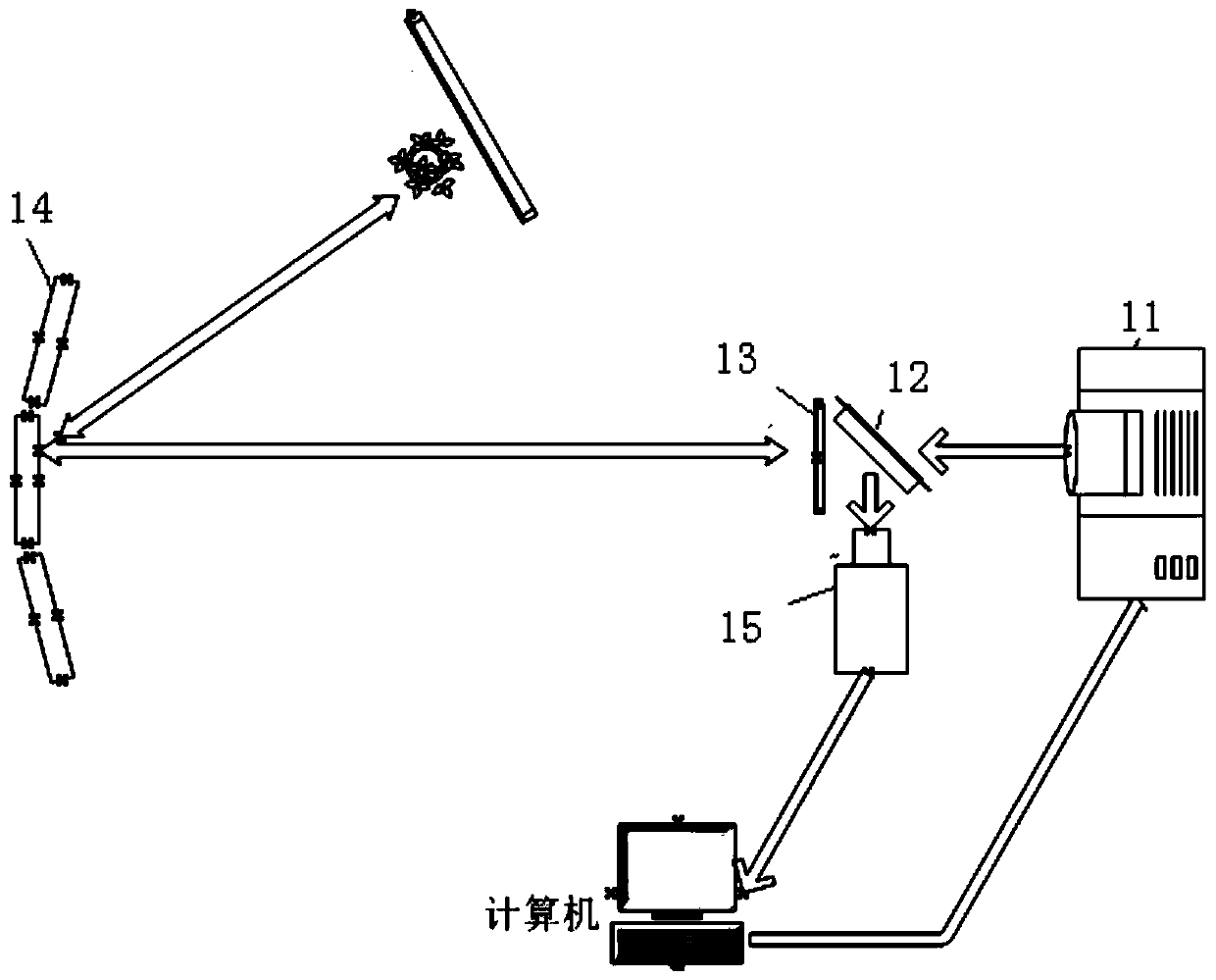
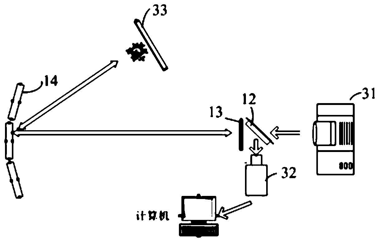
[0031] Although the confocal encoding method in the background art can expand the imaging range, and because the confocal illumination does not need to be scanned, the confocal imaging process is simple and fast. However, since the plane mirror array in the confocal encoding method is fixed and cannot be adjusted, it is not simple and flexible enough, which limits the application scenarios of confocal imaging. Therefore, in order to solve this problem, the embodiment of the present invention adopts the aperture imaging method to solve the cumbersome problem of the scanning illumination process, and sets an adjustable plane mirror array, and uses the adjustment of the plane mirror array to overcome the problem that the confocal illumination cannot be shif...


PUM


Abstract

The invention discloses a confocal imaging device and a confocal imaging method. In the embodiment of the invention, a problem of a tedious scanning lighting process is solved through an aperture imaging method, moreover, a regulable plane mirror array is arranged, a problem of failure in passing of confocal lighting is overcome through regulation of the plane mirror array, confocal imaging underscenes, such as underwater scene, are realized, and the application scene range is expanded.

Description

technical field [0001] The invention relates to the field of computer technology, in particular to a confocal imaging device and a confocal imaging method. Background technique [0002] Confocal means that the light path including excitation and emission is brought into focus at two locations. During confocal imaging, excitation light is focused on the sample surface, while emission light is focused on the illumination pinhole. This pinhole limits the focus depth of the optical path on the sample surface, effectively preventing background noise interference from impurity signals, thereby reducing the intensity of the background signal and improving the imaging quality of the sample. The confocal imaging method was first applied to confocal microscopy, which mainly uses focused mode illumination and simultaneous imaging to create three-dimensional cross-sections of biological specimens. It is an optical imaging method that uses light focusing illumination and illumination p...

Claims


Application Information

Patent Timeline
Patent Type & Authority Applications(China)
IPC IPC(8): G01N21/21G02B26/08
CPCG01N21/21G02B26/0816
Inventor 刘宾项祎祎韩焱潘晋孝王黎明陈平魏交统苏新彦
Owner ZHONGBEI UNIV
Why Eureka
Try Eureka