Stirring mill

A grinding machine and grinding technology, which is applied in the direction of mixers, mixers with rotating stirring devices, dissolution, etc., can solve the problems that the grinding auxiliary body cannot be fully uniform

Active Publication Date: 2019-09-03
耐驰精细研磨技术有限公司
View PDF8 Cites 1 Cited by
  • Summary
  • Abstract
  • Description
  • Claims
  • Application Information

AI Technical Summary

Problems solved by technology

A sufficiently uniform and crush-free distribution of the grinding aids in the grinding chamber has not yet been achieved by this known measure

Method used


Image

  • Stirring mill
  • Stirring mill
  • Stirring mill

Examples


Embodiment Construction

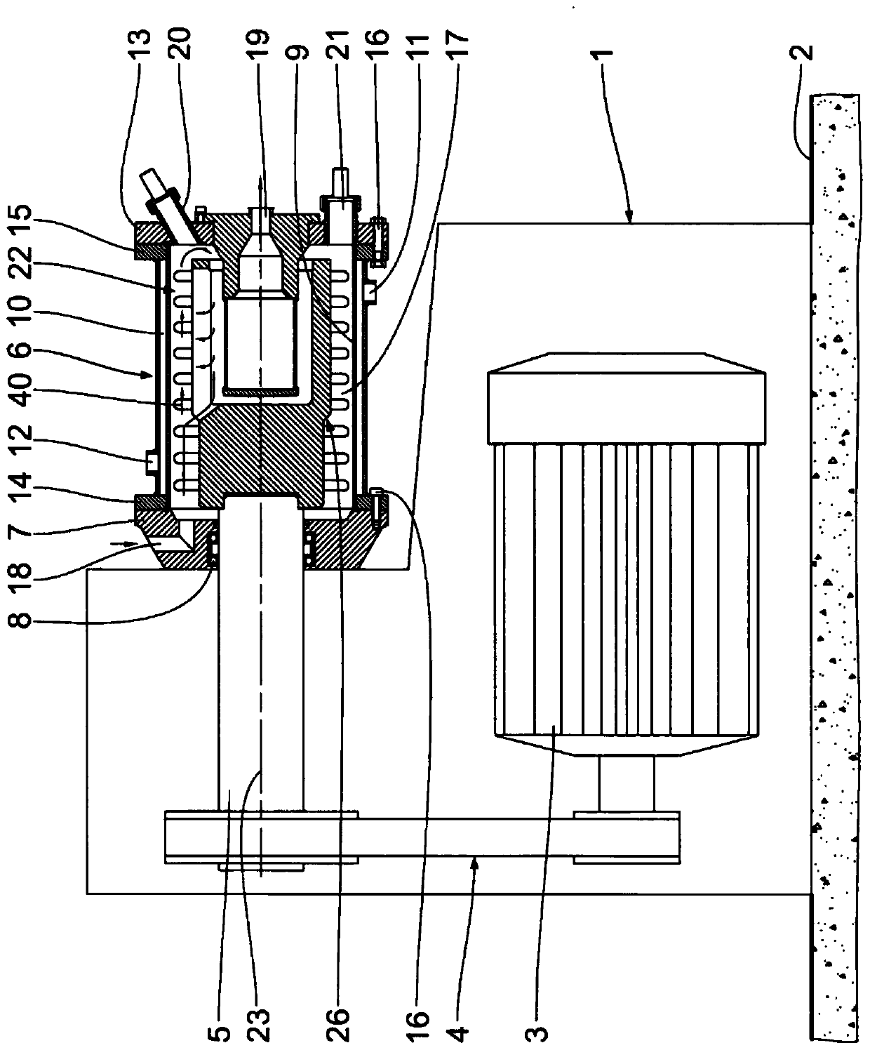
[0021] as available from figure 1 As seen in the figure, a horizontal agitating mill has a frame 1 supported on the ground 2 . Arranged in the lower region of the machine frame 1 is a drive motor 3 , which is coupled to a drive shaft 5 by means of a belt drive 4 .

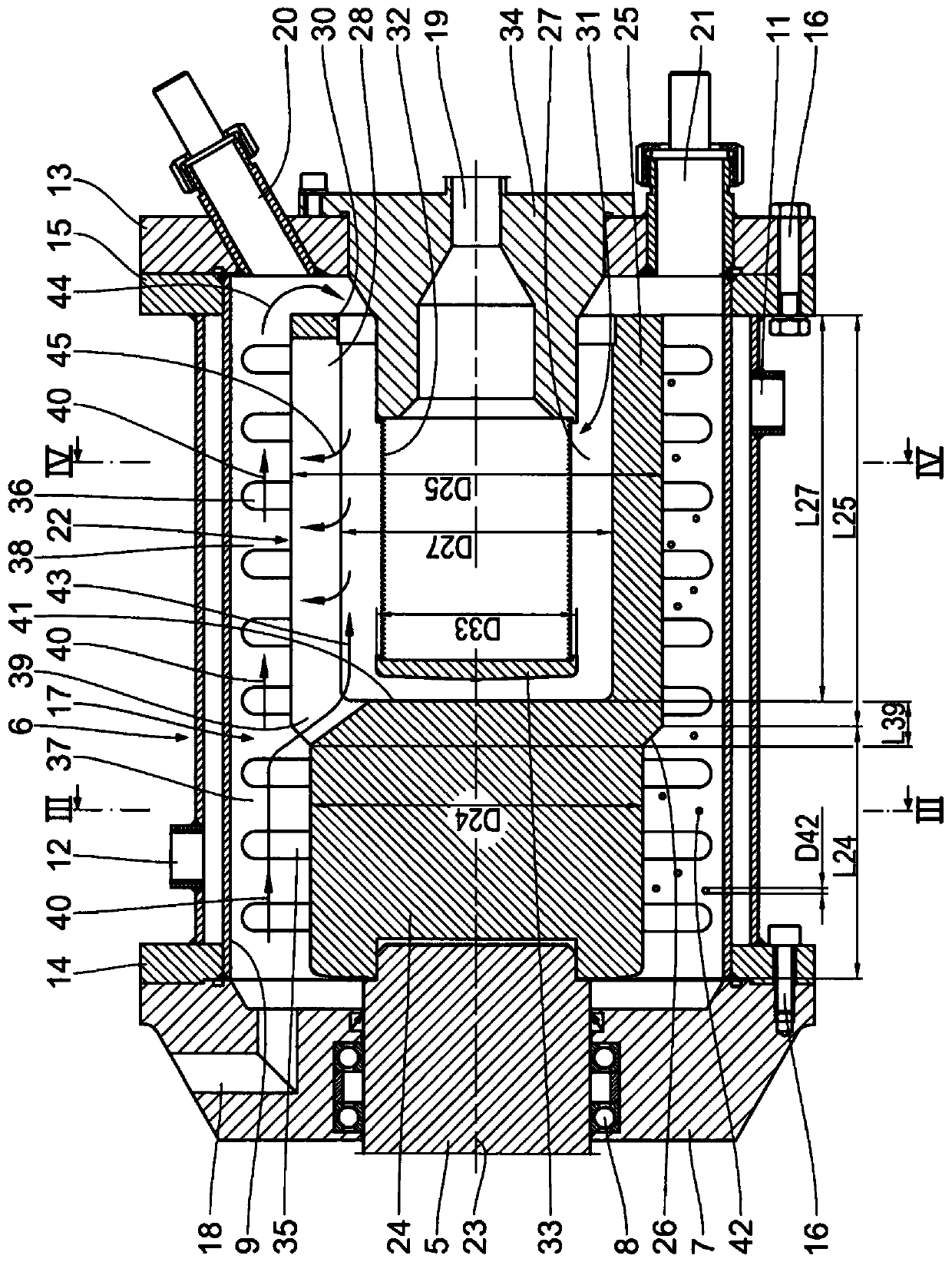
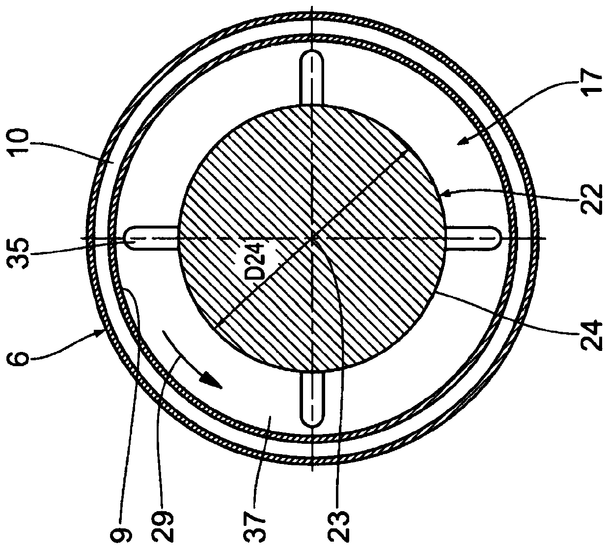
[0022] In the upper region of the frame 1 a horizontal grinding container 6 is fastened to the frame. The grinding container has a first grinding container housing 7 which is mounted on the machine frame 1 and in which the drive shaft 5 is rotatably mounted by means of a roller bearing 8 . The grinding container 6 also has a cylindrical inner wall 9 which is surrounded by a temperature-controlling housing 10 into which a temperature-controlling agent, usually coolant, is introduced via an inlet 11 and discharged via an outlet 12 . At the end opposite the first grinding container cover 7 , ie at a distance from the upper region of the machine frame 1 , the grinding container 6 is closed by a second grinding contai...


PUM


Abstract

The invention relates to a stirring mill. The stirring mill comprises a horizontally arranged milling vessel (6) and a stirring shaft (22) which is arranged therein so that it can be rotationally driven. The stirring shaft (22) has a first stirring shaft section (24) adjacent to an inlet for material to be ground (18), which has a smaller diameter D24, and a second stirring shaft section (25) adjacent to an outlet for material to be ground (19), which has a larger diameter D25 and in which a separating device (31) is formed. Bypass channels (39') leading into the separating device (31) are formed in the first stirring shaft section (24).

Description

technical field [0001] The invention relates to an agitating mill comprising: a horizontally arranged grinding container with a cylindrical inner wall; Driven stirring shaft; a grinding chamber defined by the inner wall and the stirring shaft, wherein the grinding material inlet leads into the grinding chamber at the first end of the grinding chamber, wherein the grinding material outlet is connected to the grinding container at the second A second end of the opposite grinding container is passed out, wherein the agitating shaft has a first agitating shaft section with a smaller diameter D24 defining the first grinding chamber area adjacent to the grinding material inlet and is connected to the grinding material inlet. The second agitating shaft section with a larger diameter D25 defining the second grinding chamber area adjacent to the grinding material outlet, wherein: D25>D24, wherein the second agitating shaft section has a cavity, and the cavity is opposite to each oth...

Claims


Application Information

Patent Timeline
Patent Type & Authority Applications(China)
IPC IPC(8): B02C17/16
CPCB02C17/163B01F27/60B02C17/16B01F27/212B01F33/80B01F33/83613B02C2017/165B02C17/161
Inventor H·波许G·科勃H·默舍尔U·恩德勒W·祖德曼L-P·韦兰
Owner 耐驰精细研磨技术有限公司
Why Eureka
Try Eureka