
An automatic safety collection system for hazardous waste incineration slag

A technology for incinerating slag and hazardous waste, which is applied in the field of automatic and safe collection system for hazardous waste incineration slag, which can solve problems such as adverse health and environmental effects, failure to meet technical requirements, and large production volume, so as to avoid waste, improve adsorption efficiency, and produce high efficiency effect

Active Publication Date: 2021-01-26
镇江新宇固体废物处置有限公司
View PDF12 Cites 0 Cited by
  • Summary
  • Abstract
  • Description
  • Claims
  • Application Information

AI Technical Summary

Problems solved by technology

However, the by-product slag produced in the incineration process (including the incineration residue remaining on the grate and the particles falling from between the grate) is still relatively large (accounting for about 20% to 30% of the mass of garbage) due to its abundant resources. ), and has a certain degree of pollution to the environment, so it has attracted more and more attention, and many experts and scholars have conducted in-depth research on its resource utilization
[0003] Existing research and engineering practice have shown that resource utilization of slag is feasible, but since slag contains a certain amount of Fe, non-ferrous metals (mainly Cu, Al) and unburned residual garbage, if direct utilization is possible It will cause adverse effects on human health and the environment. In addition, because the existence of these substances cannot meet the technical requirements stipulated for resource utilization, the slag must be sorted and pretreated before resource utilization to recycle Fe. , Cu, Al and other waste metals, separate and collect unburned residual garbage, and properly dispose of them

Method used


Image

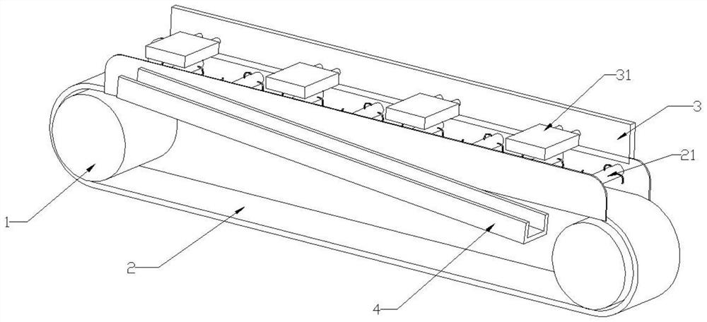
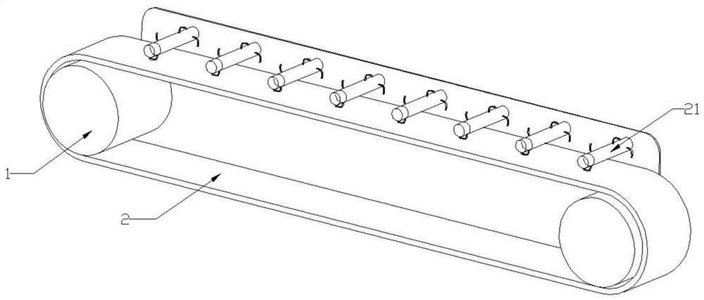
  • An automatic safety collection system for hazardous waste incineration slag
  • An automatic safety collection system for hazardous waste incineration slag
  • An automatic safety collection system for hazardous waste incineration slag

Examples


Embodiment Construction

[0022] In order to deepen the understanding of the present invention, the present invention will be further described below in conjunction with the embodiments and accompanying drawings. The embodiments are only used to explain the present invention, and do not constitute a limitation to the protection scope of the present invention.

[0023] An automatic safety collection system for hazardous waste incineration slag, including a feeder connected in sequence, a roller screen 5, a multi-stage iron remover, a jig and a dryer;

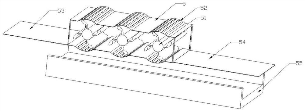
[0024] Such as image 3 As shown, the roller sieve includes a main sieve body, and the main sieve body is connected with a plurality of arc-shaped sieve walls, and the sieve walls are provided with a plurality of elongated slots, and above the sieve walls There is a rotating shaft, four L-shaped blades are connected to the outer wall of the rotating shaft, a second conveyor belt is provided under the main screen body, and the main conveyor belt and the fi...


PUM


Abstract

The invention discloses an automatic safe collection system for hazardous waste incineration furnace slag. The automatic safe collection system for the hazardous waste incineration furnace slag comprises a feeder, a roller screen, a multi-stage iron remover, a jigger and a dryer which are sequentially connected, wherein the feeder is used for conveying materials into the roller screen; through theaction of the roller screen, the furnace slag with large diameters is cleaned out, and the furnace slag with proper diameters is reserved; then iron, nickel and other magnetic metals in the furnace slag are adsorbed through the multi-stage iron remover and by virtue of the adsorption effect of a magnet; and then copper, aluminum and other precious metals with high densities are cleaned out through the jigger, and the remainder waste slag is dried through the dryer, so that the storage cost can be saved. The device is capable of effectively recovering the precious metal components in the furnace slag, thereby turning waste into wealth, and reducing the floor area of the waste furnace slag.

Description

technical field [0001] The invention relates to an automatic safety collection system for hazardous waste incineration slag. Background technique [0002] In recent years, many cities in my country have built and put into operation domestic waste incineration power plants. Through incineration, the volume of waste has been greatly reduced, the toxic substances in the waste have been completely incinerated, and the waste heat generated by incineration has been recycled and utilized. However, the by-product slag produced in the incineration process (including the incineration residue remaining on the grate and the particles falling from between the grate) is still relatively large (accounting for about 20% to 30% of the mass of garbage) due to its abundant resources. ), and has a certain degree of pollution to the environment, so it has attracted more and more attention, and many experts and scholars have conducted in-depth research on its resource utilization. [0003] Exist...

Claims


Application Information

Patent Timeline
Patent Type & Authority Patents(China)
IPC IPC(8): B03B7/00B03C1/30F23J1/02F23J1/06
CPCB03B7/00B03C1/30F23J1/02F23J1/06
Inventor 殷亚星张建军潘敏
Owner 镇江新宇固体废物处置有限公司
Learn More