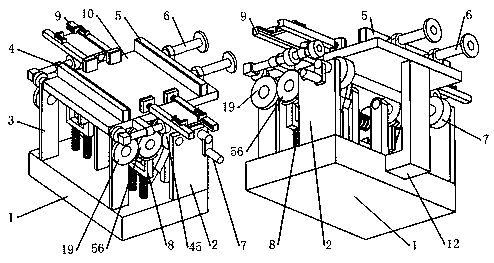
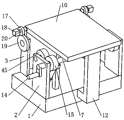
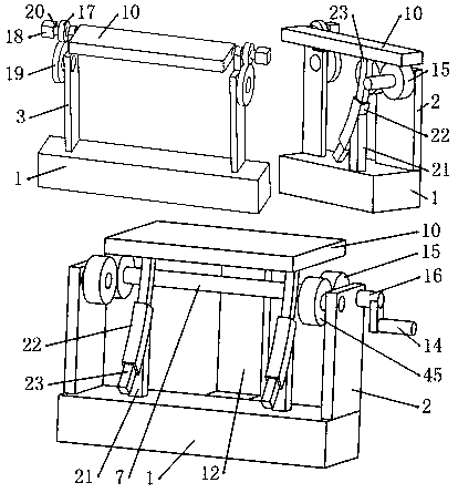
Adjustable die holder for machining workpieces

A technology for processing workpieces and mold seats, applied in the field of adjustable mold seats, can solve the problems of inconvenient use, unsuitable fixing of clamping parts, difficult processing, etc. process, the effect of speeding up the processing efficiency

Pending Publication Date: 2019-09-06
HANGZHOU DIANZI UNIV
View PDF5 Cites 2 Cited by
  • Summary
  • Abstract
  • Description
  • Claims
  • Application Information

AI Technical Summary

Problems solved by technology

[0002] At present, the workpieces produced and processed by the mold often need to be finished according to a certain angle, and the existing processing method is often to design and process an inclined die according to the specified angle, and then process the workpiece through the inclined die with an inclined angle. The processing method is not universal. When it is necessary to produce workpieces with different angles, a diagonal mold with a fixed angle must be produced separately. There are problems such as waste of materials and difficult processing.
[0003] For example, the "adjustable mold" with the patent No. "CN 104118133 B" is the solution to the above-mentioned problems, but this patent uses a combination of multiple screws and nuts when actually fixing the workpiece processed by the mold and adjusting the angle of the rotating plate. structure to fix the adjusted position, or use the structure of screws and nuts to fix the workpiece on the rotary plate; while the structures of multiple screws and nuts need to be adjusted manually; in actual use, multiple screws and nuts The adjustment of the structure is very cumbersome and not convenient to use
In addition, this patent fixes the workpiece with clamping parts distributed in the circumferential direction, but for workpieces with a high height, the clamping parts cannot adapt to the fixing of such workpieces.

Method used


Image

  • Adjustable die holder for machining workpieces
  • Adjustable die holder for machining workpieces
  • Adjustable die holder for machining workpieces

Examples


Embodiment Construction

[0044] The present invention will be described below with reference to the accompanying drawings; however, it should be understood that these descriptions are illustrative only and are not intended to limit the scope of the present disclosure. Also, in the following description, descriptions of well-known structures and techniques are omitted to avoid unnecessarily obscuring the concept of the present disclosure. All terms (including technical and scientific terms) used herein have the meaning commonly understood by one of ordinary skill in the art, unless otherwise defined. It should be noted that the terms used herein should be interpreted to have a meaning consistent with the context of this specification, and not be interpreted in an idealized or overly rigid manner. The structures in the accompanying drawings of the present invention are only schematic, and are not limited to specific proportions, shapes, and installation relationships; the structures in the accompanying ...


PUM


Abstract

The invention belongs to the field of die processing, and particularly relates to an adjustable die holder for processing workpieces. The adjustable die holder comprises an A support, an adjusting mechanism, a B support, a driving mechanism, an extruding mechanism, a moving mechanism and the like; the swing of the die holder can be distinguished from the extruding of the extruding mechanism through the design that a connecting rod presses down or not, so that the adjusting mechanism has two different output adjusting modes; the effect of maintaining the extruding mechanism to extrude the workpieces is achieved through the matching design of unidirectional teeth on a arc strip and a D gear; and in addition, due to the design of the extruding mechanism, a baffle, a extruding plate and the moving mechanism, the workpieces with different widths can be well extruded and fixed so as not to move during processing. Compared with the prior art, swing adjustment of the die holder and the extrusion fixing of the workpieces can be operated very conveniently, the process of complex adjustment of a plurality of screws and nuts in the prior art is greatly simplified, and the processing efficiencyof the workpieces is greatly improved.

Description

technical field [0001] The invention belongs to the field of mold processing, and in particular relates to an adjustable mold seat for processing workpieces. Background technique [0002] At present, the workpieces produced and processed by the mold often need to be finished according to a certain angle, and the existing processing method is often to design and process an inclined die according to the specified angle, and then process the workpiece through the inclined die with an inclined angle. The processing method is not universal. When it is necessary to produce workpieces with different angles, it is necessary to separately produce a fixed-angle inclined die, which has problems such as waste of materials and difficult processing. [0003] For example, the "adjustable mold" with the patent No. "CN 104118133 B" is the solution to the above-mentioned problems, but this patent uses a combination of multiple screws and nuts when actually fixing the workpiece processed by th...

Claims


Application Information

Patent Timeline
IPC IPC(8): B21D37/04B21D43/00
CPCB21D37/04B21D43/003
Inventor 叶剑涛管越峰连升炯鲁豪董李杰
Owner HANGZHOU DIANZI UNIV
Why Eureka
Try Eureka