
CNC lathe fly-cutter disk and assembling method thereof

A technology of flying cutter head and cutter head, applied in the direction of tool holder, etc., can solve the problems of inability to achieve high processing precision and high quality, ordinary cutter head does not have adjustment conditions, reducing the processing efficiency of flying cutter head, etc., to ensure concentricity. and finish, improve processing performance, simple installation effect

Inactive Publication Date: 2019-09-06
邹洪波
View PDF5 Cites 1 Cited by
  • Summary
  • Abstract
  • Description
  • Claims
  • Application Information

AI Technical Summary

Problems solved by technology

[0003] Flying cutter head is an essential and important part in the process of CNC lathe processing. It is an important structure for cutting and processing the surface of the product. When processing the disc, only a single tool can be used to work, which not only greatly reduces the processing efficiency of the flying cutter disc, but also requires multiple processing of the product, which reduces the processing performance; at the same time, ordinary cutter discs do not have adjustment conditions at all. Therefore, it is impossible and impossible to achieve the purpose of processing high precision and high quality for relatively complex workpieces.

Method used


Image

  • CNC lathe fly-cutter disk and assembling method thereof
  • CNC lathe fly-cutter disk and assembling method thereof
  • CNC lathe fly-cutter disk and assembling method thereof

Examples


Embodiment Construction

[0031] The technical scheme of the present invention will be described in further detail below in conjunction with the accompanying drawings and specific examples, so that those skilled in the art can better understand the present invention and implement it, but the examples given are not intended to limit the present invention In addition, the terms "first", "second", "above", "bottom" and the like are used for descriptive purposes only, and should not be construed as indicating or implying relative importance.

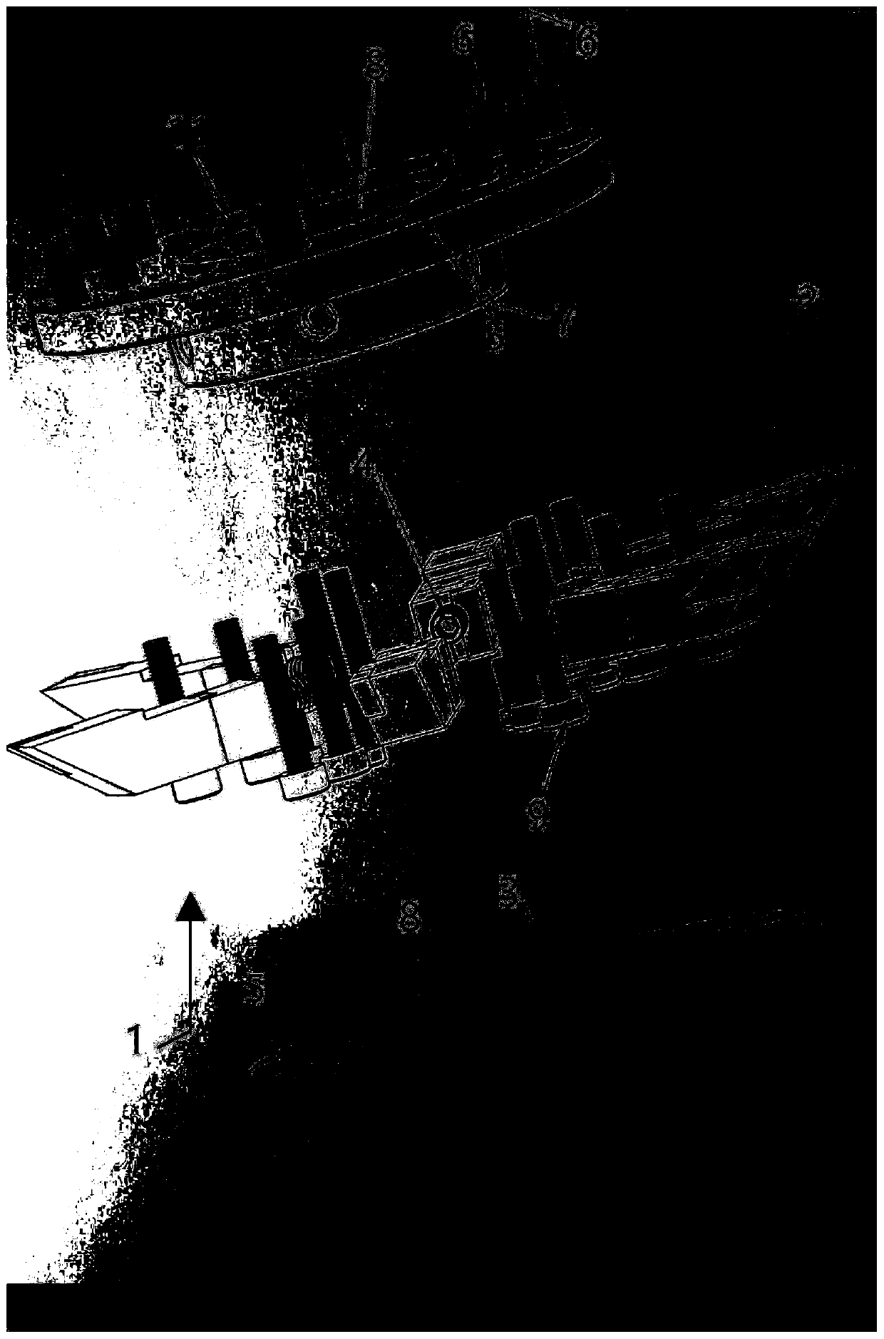
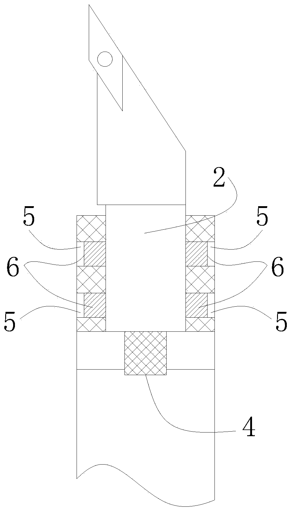
[0032] Please refer to figure 1 and image 3 , the embodiment of the present invention provides a CNC lathe flying cutter head, including a cutter head body 1 and a plurality of cutter bar assemblies 2, since the cutter head body 1 is provided with a plurality of cutter bar assemblies 2, the flying cutter head can be effectively improved. Processing efficiency and processing performance, the cutter head body 1 is provided with a plurality of installation grooves 3 t...


PUM


Abstract

The invention relates to a CNC lathe fly-cutter disk. The CNC lathe fly-cutter disk comprises a cutter disk body and a plurality of cutter rod assemblies; a plurality of mounting grooves matched withthe cutter rod assemblies are formed in the cutter disk body; the cutter rod assemblies are positioned in the mounting grooves; the cutter disk body is connected with an adjusting piece for controlling the cutter rod assemblies to draw back and stretch out; a plurality of limiting holes communicating with the mounting grooves are formed at the upper end and the lower end of the cutter disk body; and a limiting block is arranged in single limiting hole and the limiting block can draw back and stretch out from the limiting hole. The CNC lathe fly-cutter disk provided by the embodiment of the invention has extremely high processing efficiency and processing property and can adjust the cutter disk to guarantee high precision and high quality of a processing workpiece.

Description

technical field [0001] The invention relates to the technical field of machine tools, in particular to a CNC lathe flying cutter head and an assembly method thereof. Background technique [0002] Numerical control equipment CNC lathes have a long history of development, and multi-functional CNC lathes are also heading towards the peak. For CNC lathe processing, first determine the process requirements of the parts, the batch of processed workpieces, formulate the functions that the CNC lathe should have, and make preliminary preparations. The premise of a reasonable selection of CNC lathes Conditions to meet the process requirements of typical parts The process requirements of typical parts are mainly the structural size, processing range and accuracy requirements of the part. [0003] Flying cutter head is an essential and important part in the process of CNC lathe processing. It is an important structure for cutting and processing the surface of the product. When processi...

Claims


Application Information

Patent Timeline
IPC IPC(8): B23B29/24
CPCB23B29/248
Inventor 邹洪波
Owner 邹洪波
Learn More