
Anti-theft window

An anti-theft window and anti-theft rod technology, applied in the field of anti-theft windows, can solve problems such as troublesome operation of the anti-theft window

Active Publication Date: 2019-09-06
李晨曦
View PDF11 Cites 3 Cited by
  • Summary
  • Abstract
  • Description
  • Claims
  • Application Information

AI Technical Summary

Problems solved by technology

[0005] The object of the present invention is to provide an anti-theft window to solve the problem of troublesome operation of the anti-theft window in the prior art due to frequent inflation and deflation

Method used


Image

  • Anti-theft window
  • Anti-theft window
  • Anti-theft window

Examples


Embodiment Construction

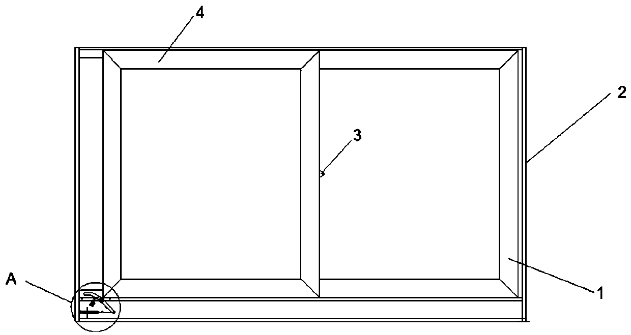
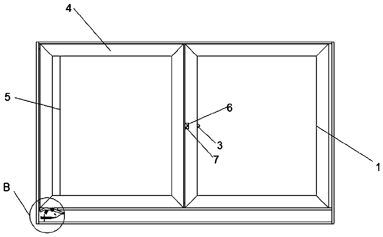
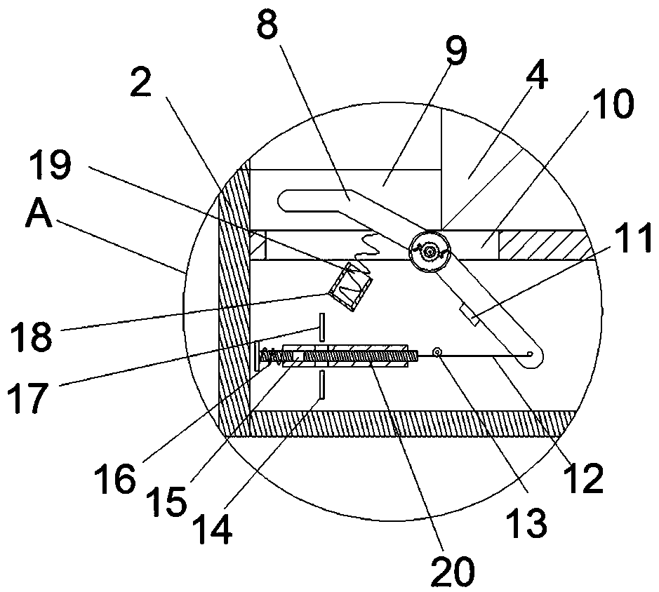
[0026] The embodiment of anti-theft window in the present invention is such as Figure 1~8 Shown: comprise window frame 2, the right side of window frame is fixedly provided with fixed window 1, and the top, bottom of window frame are provided with the push-pull track 9 that extends along the left and right direction at the rear side of described fixed window, guide on the push-pull track 9 Mobile device is equipped with movable sliding window 4. The fixed window 1 and the movable sliding window 4 both include a glass frame and the glass fixed on the inner side of the glass frame. The left and right sides of the glass frame of the fixed window are arranged with a first lock 7 and a second lock 3 at intervals, and the right side of the movable sliding window Sliding window locks (not shown in the figure) are provided at different positions for locking and cooperating with the first lock and the second lock respectively. In this embodiment, the sliding window locks are commonly ...


PUM


Abstract

The invention relates to ananti-theft window.The upper end of an anti-theft bar extends intoa push-pull track on the lower side, the anti-theft window further comprises a laser alarm, the laser alarmcomprises a laser transmitter and a laser emitting circuit of a first power source, the laser alarm further comprises a receiving detecting circuit, the receiving detecting circuit comprises a receiving detecting circuit switch contact, an alarm device, and a photoresistor arranged opposite to the laser emitting circuit, the anti-theft rod is connected with a light blocking member located betweenthe laser emitting circuit and the photoresistor in a transmission mode, a light-transmitting holeis formed in the light blocking member,a movable sliding windowpushes the anti-theft rod in a jackingmode in the process of leftwards moving from a normal station to an anti-theft station to enable the anti-theft rod to rotate to be in joint with the receiving and detecting circuit switch contact, alaser of the laser transmitteris emitted to the photoresistor through the light-transmitting hole,and the light blocking memberis rest to block the laser in the process that the movable sliding windowmoves rightwards from the anti-theft station to the normal station.According to the anti-theft window, the problem thatin the prior art, the anti-theft window is inflated and deflated frequently dueto the need, and consequently operation is troublesome is solved.

Description

technical field [0001] The invention relates to an anti-theft window in the field of home anti-theft. Background technique [0002] In recent years, the speed of urbanization in my country has continued to accelerate, and the urban population has continued to increase. Many factors have led to the current unsatisfactory public security situation in the community, which seriously threatens the safety of life and property of urban residents. The smart door lock devices currently on the market are not only very expensive, but also helpless for window prying and theft, and are not suitable for the use of urban residents. [0003] The Chinese patent whose publication number is CN103996259B and whose application name is "Multi-point Control Pneumatic Door and Window Anti-theft Alarm Trigger Device" discloses an anti-theft device suitable for doors and windows, which includes a hard tube, a flexible tube arranged in the hard tube, and a puncture needle. The elastic device has a lo...

Claims


Application Information

Patent Timeline
IPC IPC(8): E06B5/11E06B3/46E05B65/08G08B13/08
CPCE05B65/08E06B3/4618E06B5/113G08B13/08
Inventor 李晨曦李博宇冯俊锋
Owner 李晨曦
Learn More