A large transmission ratio reduction method and device
What is AI technical title?
AI technical title is built by Patsnap AI team. It summarizes the technical point description of the patent document.
A technology of large transmission ratio and reduction gear, applied in the direction of transmission, gear transmission, transmission parts, etc., can solve the problems of large size, high cost, short life and so on
Active Publication Date: 2021-08-20
保定启晨传动科技有限公司
View PDF9 Cites 0 Cited by
Summary
Abstract
Description
Claims
Application Information
AI Technical Summary
This helps you quickly interpret patents by identifying the three key elements:
Problems solved by technology
Method used
Benefits of technology
Problems solved by technology
[0002] The reducer is an independent component composed of gear transmission, worm transmission, and gear-worm transmission enclosed in a rigid shell. It is often used as a reduction transmission device between the prime mover and the working machine. Mechanisms play the role of matching speed and transmitting torque. They are widely used in modern machinery. With the development of mechanical technology, the technology of reducers is also improving. There are various reducers on the market, but the existing The high-speed ratio reducers of today have defects such as large size, heavy weight, unfavorable installation, short life, and high cost. At present, the market is in urgent need of a large speed ratio with small size, light weight, low cost, long life, stability and reliability. reducer
Method used
Image
Click on the blue label to locate the original text in one second.
Reading with bidirectional positioning of images and text.
Examples
Embodiment 1
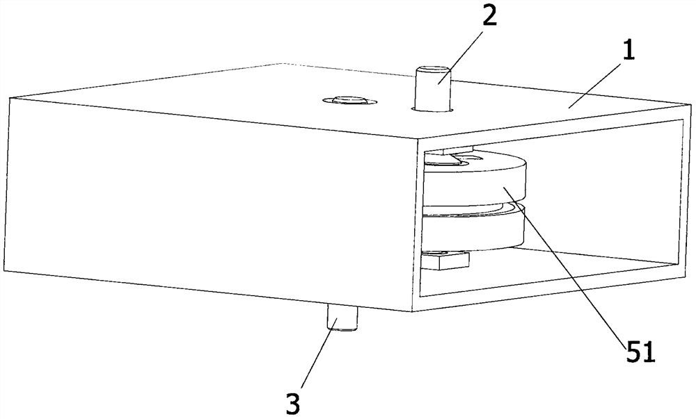
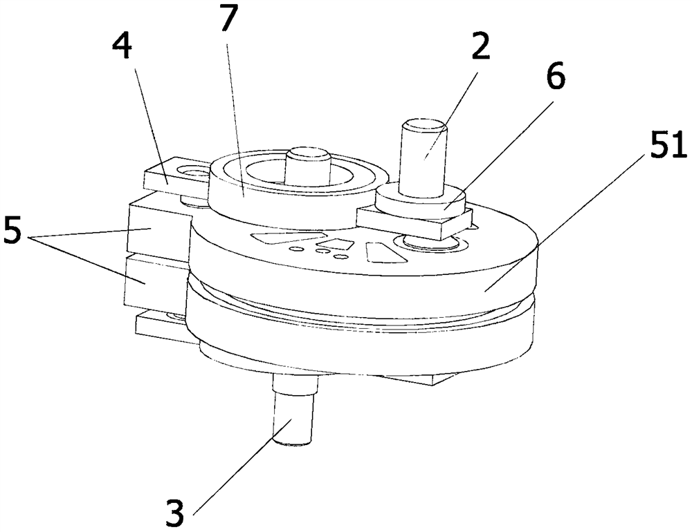
[0049] Such as Figure 1~4 As shown, a large transmission ratio reduction device, including a box 1;
[0050] an input shaft 2, the input shaft 2 is rotatably arranged on the box body 1;
[0051] an output shaft 3, the output shaft 3 is rotatably arranged on the box body 1;
[0052] The first turret 4, the first turret 4 is rotatably arranged on the box body 1, the rotating shaft of the first turret 4 around the box body 1 and the output shaft 3 around the box body 1. The rotating shafts are not on the same axis;
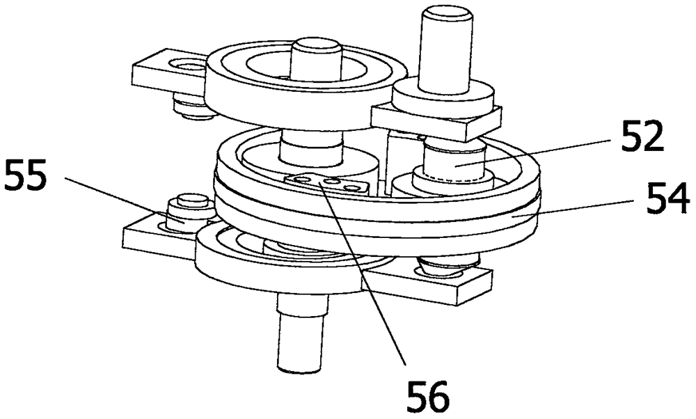
[0053] The first transmission group 5 , the first transmission group 5 is arranged on the first turret 4 , and the first transmission group 5 is used to link the first turret 4 and the output shaft 3 .
[0054] In this embodiment, the input shaft 2 and the first turret 4 are installed on the box body 1, power is input through the input shaft 2, and the input shaft 2 is fixedly arranged on the first turret 4 through the second gear 6 fixedly connected thereto. Th...
Embodiment 2
[0067] Such as Figure 5-9 As shown, a large transmission ratio reduction device, including a box 1;
[0068] an input shaft 2, the input shaft 2 is rotatably arranged on the box body 1;
[0069] An output shaft 3, the output shaft 3 is rotatably arranged on the box body 1, and the output shaft 3 and the input shaft 2 are not coaxially arranged on the box body 1;
[0070] The second turret 91, one side of the second turret 91 is rotatably arranged with the box body 1, and the other side of the second turret 91 is rotatably connected with the input shaft 2;
[0071] The third turret 92, one side of the third turret 92 is rotatably arranged on the box body 1, the other side of the third turret 92 is rotatably arranged with the output shaft 3, the third turret 92 is not coaxial with the rotating shaft of the casing 1 and the rotating shaft of the second turret 91 and the casing 1;
[0072] The second ring gear 10 , the second ring gear 10 is fixedly arranged on the casing 1 , ...
PUM
Abstract
The invention belongs to the technical field of reducers, and proposes a large transmission ratio deceleration method and device, including a method for realizing deceleration by constructing a driving gear that only revolves around a fixed shaft and does not rotate itself, and includes a method based on the principle of parallelogram to form The method for the effect of only revolution without rotation also includes the box; the input shaft, the input shaft is rotatably set on the box; the output shaft, the output shaft is rotatably set on the box; the first turret, the first turret is rotatably set on the box On the body: the first transmission group, the first transmission group is arranged on the first turret, and the first transmission group is used to link the first turret and the output shaft. Through the above technical solution, the problems of single transmission ratio and uncompact structure of the reducer in the prior art are solved.
Description
technical field [0001] The invention belongs to the technical field of reducers, and relates to a large transmission ratio reduction method and device. Background technique [0002] The reducer is an independent component composed of gear transmission, worm transmission, and gear-worm transmission enclosed in a rigid shell. It is often used as a reduction transmission device between the prime mover and the working machine. Mechanisms play the role of matching speed and transmitting torque, and are widely used in modern machinery. With the development of mechanical technology, the technology of reducers is also improving. There are various reducers on the market, but the existing The high-speed ratio reducers of today have defects such as large size, heavy weight, unfavorable installation, short life, and high cost. At present, the market urgently needs a large speed ratio with small size, light weight, low cost, long life, stability and reliability. reducer. Contents of t...
Claims
Application Information
Patent Timeline
Application Date:The date an application was filed.
Publication Date:The date a patent or application was officially published.
First Publication Date:The earliest publication date of a patent with the same application number.
Issue Date:Publication date of the patent grant document.
PCT Entry Date:The Entry date of PCT National Phase.
Estimated Expiry Date:The statutory expiry date of a patent right according to the Patent Law, and it is the longest term of protection that the patent right can achieve without the termination of the patent right due to other reasons(Term extension factor has been taken into account ).
Invalid Date:Actual expiry date is based on effective date or publication date of legal transaction data of invalid patent.

