
Wearable landing protection device

A protective device and wearable technology, applied in the field of parachutes, can solve the problems of inability to actively save lives and ensure life safety.

Pending Publication Date: 2021-02-19
赵琼
View PDF0 Cites 0 Cited by
  • Summary
  • Abstract
  • Description
  • Claims
  • Application Information

AI Technical Summary

Problems solved by technology

[0002] With the increasing demand for high-altitude operations, the construction of high-altitude buildings, urban elevated, the establishment and maintenance of power elevated equipment, high-rise maintenance operations, etc., there have always been safety risks for high-altitude operations, especially safety protection after falling. At present, the main focus is on prevention Falling, such as safety ropes and other equipment, but in the event of an accidental fall, life safety cannot be guaranteed
[0003] The problem of escape from high-rise buildings is also an important safety issue, especially in the event of an accidental fire, etc., one can only wait for professional fire rescue, and cannot take the initiative to save lives

Method used


Image

  • Wearable landing protection device
  • Wearable landing protection device
  • Wearable landing protection device

Examples


Embodiment 1

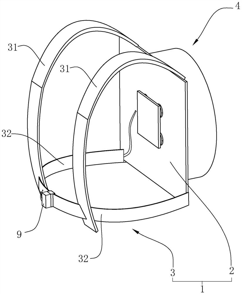
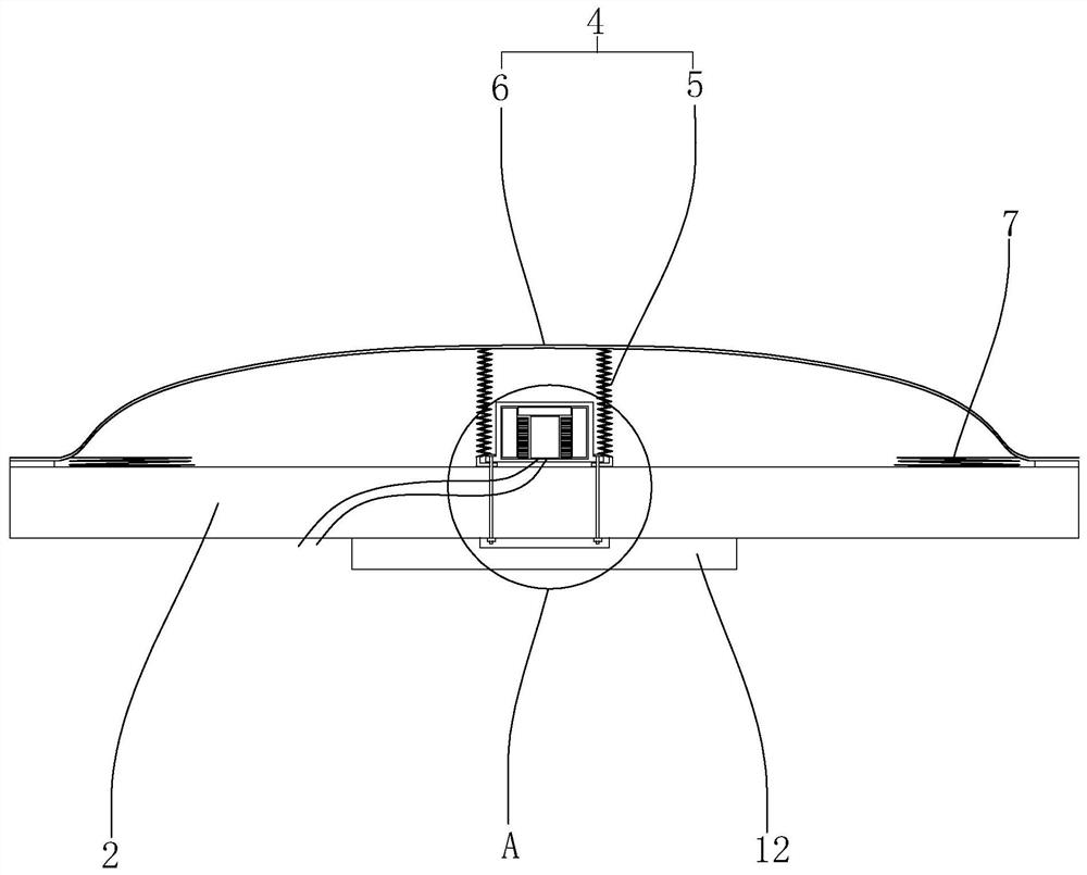
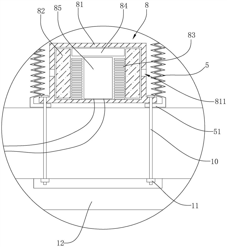
[0037] Such as Figure 1-5 As shown, a wearable fall protection device includes a wearing unit 1, an umbrella bag 4 and an inflatable device 8, wherein the wearing unit 1 includes a plate-shaped installation layer 2, and a strap assembly 3 is installed on one side of the installation layer 2, and the strap The assembly 3 includes a pair of shoulder straps 31, and a waist belt 32 is arranged on the opposite side of the shoulder straps 31. An installation frame 33 is fixed at the end of one of the waist belts 32, and a plug-in buckle 34 is fixed at the end of the other waist belt 32. The buckle 34 is detachably embedded in the installation frame 33, and the umbrella bag 4 and the inflatable device 8 are both arranged on the other side of the installation layer 2; the user is fixed on the back through the strap assembly 3, and when the protection device is not activated, the umbrella The bag 4 is in a storage state; and an intelligent control device 9 is fixed on the installation...

Embodiment 2

[0048] The difference from Example 1 is:

[0049] Such as Figure 6 As shown, the outer circumference of the umbrella surface 6 is provided with an annular cavity 64, and a memory wire 65 is threaded in the annular cavity 64, and a fixed ring 13 is extended on the side of the installation layer 2 towards the umbrella bag 4, and the inner side of the fixed ring 13 An annular protrusion 131 is provided;

[0050] When the protection device is not activated, the memory wire 65 can be arbitrarily bent and deformed on the plane where the memory wire 65 is located, and then the memory wire 65 can be snapped into the fixed ring 13, and the memory wire 65 abuts against the inner side of the annular protrusion 131 , thereby realizing the fixed purpose of the umbrella bag 4;

[0051] When the inflatable device 8 generates gas and enters the inflatable tube 5, the inflatable tube 5 pushes the umbrella surface 6 to separate from the installation layer 2, and then the elastic force of the...

Embodiment 3

[0053] The difference from Example 1 is:

[0054] Such as Figure 7 As shown, the umbrella cover 6 is made of a single layer of cloth, and a hose 66 is fixed by sewing at intervals in the circumferential direction of the umbrella cover 6, and one end of the hose 66 is communicated and fixed with the inflation tube 5, and the other end is sealed; when the inflation device 8 After starting, only a small amount of gas needs to enter the inflatable tube 5 and the flexible pipe 66, and the flexible pipe 66 forms a supporting force on the umbrella surface 6, thereby realizing the purpose of stably deploying the umbrella surface 6.


PUM


Abstract

The invention relates to a wearable landing protection device. The device comprises a wearable unit, a parachute pack and an inflating device, wherein the wearable unit comprises a platy mounting layer, the mounting layer can also be of any other fixing structure, a strap assembly is mounted on one side of the mounting layer, the strap assembly comprises a pair of shoulder straps, and a waistbandis mounted between the shoulder straps; the waistband comprises two sections which are connected through an inserting buckle or connected in a crossed mode, and the umbrella bag and the inflation device are both arranged on the other side of the installation layer; a user is fixed to the back through the strap assembly, and when the protection device is not started, the parachute pack is in a contracted state. The intelligent control device is arranged on the front side of the waistband, an acceleration sensor is arranged in the intelligent control device, whether the protection device is in aweightless state or not is judged through the acceleration sensor, when the protection device is in the weightless state, the intelligent control device sends out a starting signal, and the inflationdevice receives the starting signal and releases gas, so the umbrella bag is unfolded; therefore, the landing speed is slowed down.

Description

technical field [0001] The invention relates to the technical field of parachutes, in particular to a wearable fall protection device. Background technique [0002] With the increasing demand for high-altitude operations, the construction of high-altitude buildings, urban elevated, the establishment and maintenance of power elevated equipment, high-rise maintenance operations, etc., there have always been safety risks for high-altitude operations, especially safety protection after falling. At present, the main focus is on prevention fall, such as safety ropes and other equipment, but once an accidental fall occurs, life safety cannot be guaranteed. [0003] The problem of escape from high-rise buildings is also an important safety issue, especially in the event of an accidental fire, etc., one can only wait for professional fire rescue, and cannot take the initiative to save lives. Contents of the invention [0004] In view of the deficiencies in the prior art, one of th...

Claims


Application Information

Patent Timeline
Patent Type & Authority Applications(China)
IPC IPC(8): B64D17/72B64D17/54
CPCB64D17/54B64D17/72
Inventor 赵琼
Owner 赵琼
Learn More