
An easy-to-adjust cut-off valve

A technology of cut-off valve and connecting pipe, which is applied in the field of cut-off valves that are easy to adjust, can solve the problems of reducing the service life of the valve plug, increasing the friction between the valve plug and the connecting port, and complicated adjustment, so as to achieve the effect of flexible adjustment and use

Active Publication Date: 2020-12-22
ZHEJIANG KABO COPPER IND CO LTD
View PDF6 Cites 0 Cited by
  • Summary
  • Abstract
  • Description
  • Claims
  • Application Information

AI Technical Summary

Problems solved by technology

[0003] Problem 1: The threaded adjustment rod of the existing stop valve is fixedly connected with the valve plug, which is easy to be over-tightened during use, resulting in the threaded adjustment rod being loose, and at the same time increasing the friction between the valve plug and the connection port, reducing the service life of the valve plug;
[0004] Problem 2: The existing multi-way globe valve only has a total adjustment rod to control multiple valve plugs. When adjusting the water outlet direction, the total adjustment rod is required to control multiple valve plugs to the appropriate position, and the adjustment is more complicated.
[0005] For the problems listed above, there is no better exploration and practice results under the existing technical conditions. Therefore, it is necessary to do further exploration and practice to solve the problems listed above

Method used


Image

  • An easy-to-adjust cut-off valve
  • An easy-to-adjust cut-off valve
  • An easy-to-adjust cut-off valve

Examples


Embodiment Construction

[0019] Embodiments of the present invention will be described below with reference to the drawings. In the process, in order to ensure the clarity and convenience of illustration, we may exaggerate the width of the lines or the size of the constituent elements in the diagram.

[0020] In addition, the following terms are defined based on the functions in the present invention, and may be different according to the user's or operator's intention or practice. Therefore, these terms are defined based on the entire content of this specification.

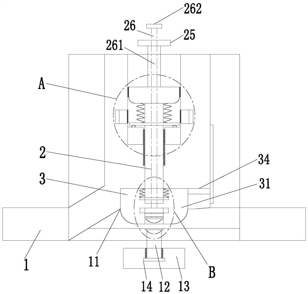
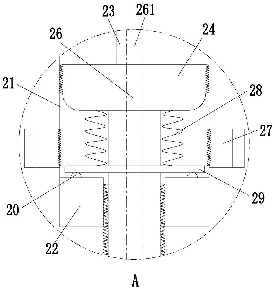
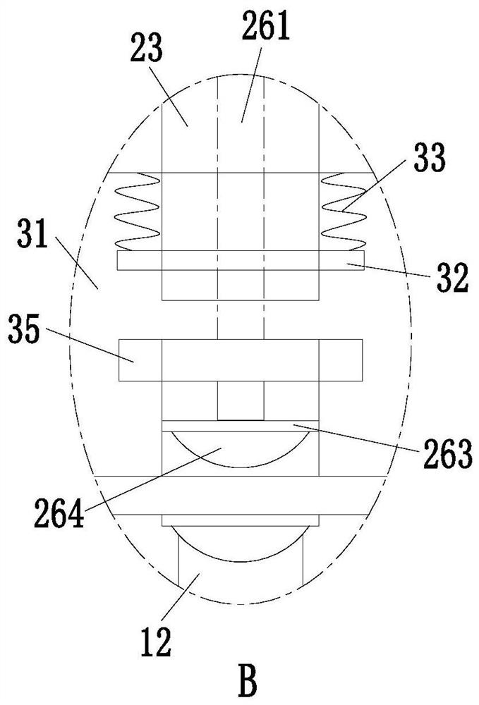
[0021] Such as Figure 1 to Figure 3 As shown, an easy-to-adjust cut-off valve includes a connecting pipe 1, a control assembly 2 and a waterproof assembly 3. The connecting pipe 1 is in an inverted T shape. The control assembly 2 is connected with a waterproof assembly 3 at the lower end of the control assembly 2 through a sliding fit.

[0022] The control assembly 2 includes a connecting cylinder 21 arranged on the inner wall of the...


PUM


Abstract

The invention relates to a stop valve convenient to adjust. The stop valve comprises a connecting pipe, a control assembly and a waterproof assembly, wherein the connecting pipe is in an inverted-T shape; the upper end of the connecting pipe is internally provided with a round groove; the round groove is internally connected with the control assembly in a threaded mode; the lower end of the control assembly is connected with the waterproof assembly in a sliding fit mode; the control assembly comprises a connecting cylinder arranged on the inner wall of the upper end of a groove; a limiting table is arranged on the inner wall of the lower end of the connecting cylinder; a control screw rod is connected inside the limiting table in a threaded mode; and the inner wall of the connecting cylinder at the upper end of the limiting table is connected with an auxiliary gear ring through a bearing. The problems that as for an existing stop valve, a threaded adjusting rod is fixedly connected with a valve plug, a worn thread occurs if screwing force is too high, the friction between the valve plug and a connecting port is increased, and the service life of the valve plug is shortened, and theproblems that an existing multi-way stop valve only has main rod adjustment function, and the adjustment is complex are solved. The stop valve is convenient to adjust and the service life is prolonged; and the stop valve has the advantages of being not prone to worn threads, long in service life and simple in flow direction adjustment.

Description

technical field [0001] The invention relates to the field of valves, in particular to an easy-to-adjust cut-off valve. Background technique [0002] The valve is an important control mechanism for fluid transportation. The valve can open and close the pipeline, control the flow direction, adjust and control the parameters of the conveying medium, etc. There are various types of valves on the market, such as shut-off valves, regulating valves, globe valves, etc. However, there are many problems in the use of globe valves in the existing market: [0003] Problem 1: The threaded adjustment rod of the existing stop valve is fixedly connected with the valve plug, which is easy to be over-tightened during use, resulting in the threaded adjustment rod being loose, and at the same time increasing the friction between the valve plug and the connection port, reducing the service life of the valve plug; [0004] Problem 2: The existing multi-way globe valve only has a total adjustment...

Claims


Application Information

Patent Timeline
Patent Type & Authority Patents(China)
IPC IPC(8): F16K1/02F16K1/36
CPCF16K1/02F16K1/36
Inventor 刘艳文马妮娜孟莉
Owner ZHEJIANG KABO COPPER IND CO LTD
Learn More