
Optical fiber vibration sensor and method for measuring vibration by adopting optical fiber vibration sensor

A fiber optic vibration and sensor technology, applied in the field of optics, can solve the problems of restricting performance consistency and practicality, and achieve the effects of good anti-electromagnetic interference, wide application fields, and simple preparation process

Inactive Publication Date: 2019-09-06
SHANGHAI MUNICIPAL ELECTRIC POWER CO +1
View PDF18 Cites 5 Cited by
  • Summary
  • Abstract
  • Description
  • Claims
  • Application Information

AI Technical Summary

Problems solved by technology

However, how to develop a sensor with simple preparation process, batch preparation and good repeatability for the practical needs of vibration sensing has always been a problem that restricts its performance consistency and practicality.

Method used


Image

  • Optical fiber vibration sensor and method for measuring vibration by adopting optical fiber vibration sensor
  • Optical fiber vibration sensor and method for measuring vibration by adopting optical fiber vibration sensor
  • Optical fiber vibration sensor and method for measuring vibration by adopting optical fiber vibration sensor

Examples


Embodiment Construction

[0033] The following will clearly and completely describe the technical solutions in the embodiments of the present invention with reference to the accompanying drawings in the embodiments of the present invention. Obviously, the described embodiments are only some, not all, embodiments of the present invention. Based on the embodiments of the present invention, all other embodiments obtained by persons of ordinary skill in the art without making creative efforts belong to the protection scope of the present invention.

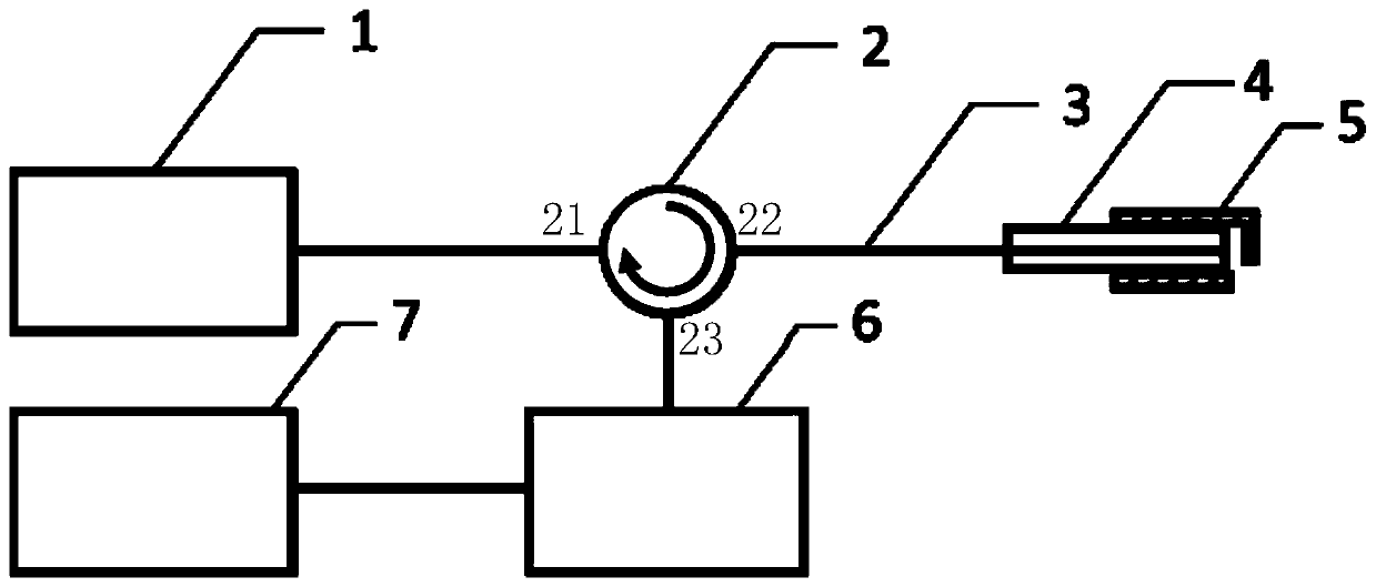
[0034] The invention provides an optical fiber vibration sensor, such as figure 1 As shown, it includes: a narrow linewidth laser 1 , a single-mode fiber 3 , an optical fiber connector 4 , a sleeve 5 , an acquisition and processing module, and an optical fiber circulator 2 .

[0035] The first end 21 of the optical fiber circulator is connected to the narrow linewidth laser 1, and the narrow linewidth laser 1 is used to output continuous light; the second end ...


PUM


Abstract

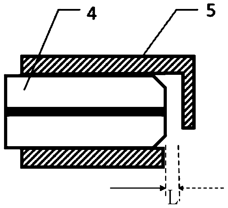
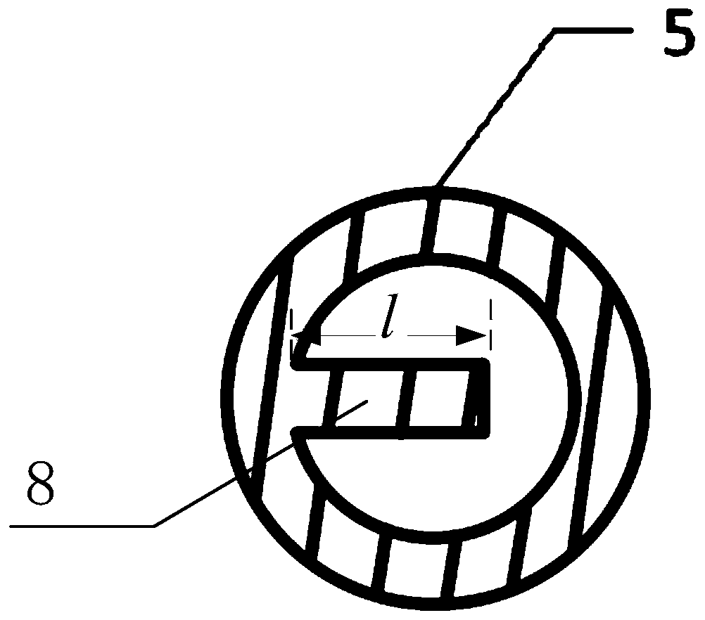
The invention provides an optical fiber vibration sensor, which comprises a narrow linewidth laser, an optical fiber circulator, a single mode fiber, an optical fiber connector, a sleeve and an acquisition and processing module. The optical fiber circulator is connected to the narrow linewidth laser, the first end of the single mode fiber and the acquisition and processing module respectively. Thesecond end of the single mode fiber penetrates through the optical fiber connector. The second end of the optical fiber connector is embedded into the first end of the sleeve. A cantilever beam is arranged on the end face of the second end of the sleeve, and a Fabry-Perot cavity is arranged between the second end of the single mode fiber and the cantilever beam. The cantilever beam senses external force to generate vibration, so that the length of the Fabry-Perot cavity changes. The continuous light output by the narrow linewidth laser enters the Fabry-Perot cavity through the optical fiber circulator and the single mode fiber. The cantilever beam reflects the continuous light and generates reflected light, and the light intensity of the reflected light changes along with the length of the Fabry-Perot cavity. The reflected light is transmitted to the acquisition and processing module through the single mode fiber and the optical fiber connector. The acquisition and processing module acquires the vibration intensity according to the light intensity of the reflected light. The optical fiber vibration sensor is high in measurement precision and simple in preparation process.

Description

technical field [0001] The invention relates to the field of optical technology, in particular to an optical fiber vibration sensor. Background technique [0002] Vibration has always been an important research topic in the field of science and technology. Vibration sensors are usually used in many fields such as seismic wave detection, fiber optic hydrophone, non-destructive testing, oil and gas exploration, industrial process control and structural health detection. Traditional vibration sensors include capacitive or piezoelectric sensors, although these sensors have high sensitivity, they are not suitable for high voltage and high magnetic field places, such as substations. Due to its natural insulation, no electrical and magnetic interference, small size, light weight, and strong multiplexing capability, the fiber optic vibration sensor has a very wide range of applications in the operation status and safety monitoring of power system facilities. Research and applicati...

Claims


Application Information

Patent Timeline
Patent Type & Authority Applications(China)
IPC IPC(8): G01H9/00B33Y30/00
CPCB33Y30/00G01H9/004G01H9/006
Inventor 邵宇鹰庞拂飞沈诗彭鹏刘奂奂王延云钱天宇郑申辉杨俊锋
Owner SHANGHAI MUNICIPAL ELECTRIC POWER CO
Learn More