Marine engine connection rod bush wear simulation test device and test method
A marine engine and connecting rod bushing technology, which is applied in the direction of engine testing, measuring devices, and testing of mechanical components, can solve problems such as large differences in force and load conditions, and achieve the effect of improving versatility and accurate test results
Pending Publication Date: 2019-09-06
WUHAN UNIV OF TECH
View PDF0 Cites 4 Cited by
- Summary
- Abstract
- Description
- Claims
- Application Information
AI Technical Summary
Problems solved by technology
[0003] Most of the test devices and test methods in the prior art use simple swing motion to simulate the motion state of the piston pin-connecting rod bushing, and only apply pulse loads
Method used
View moreImage
Smart ImageViewing Examples
Examples
 PUM
 Abstract
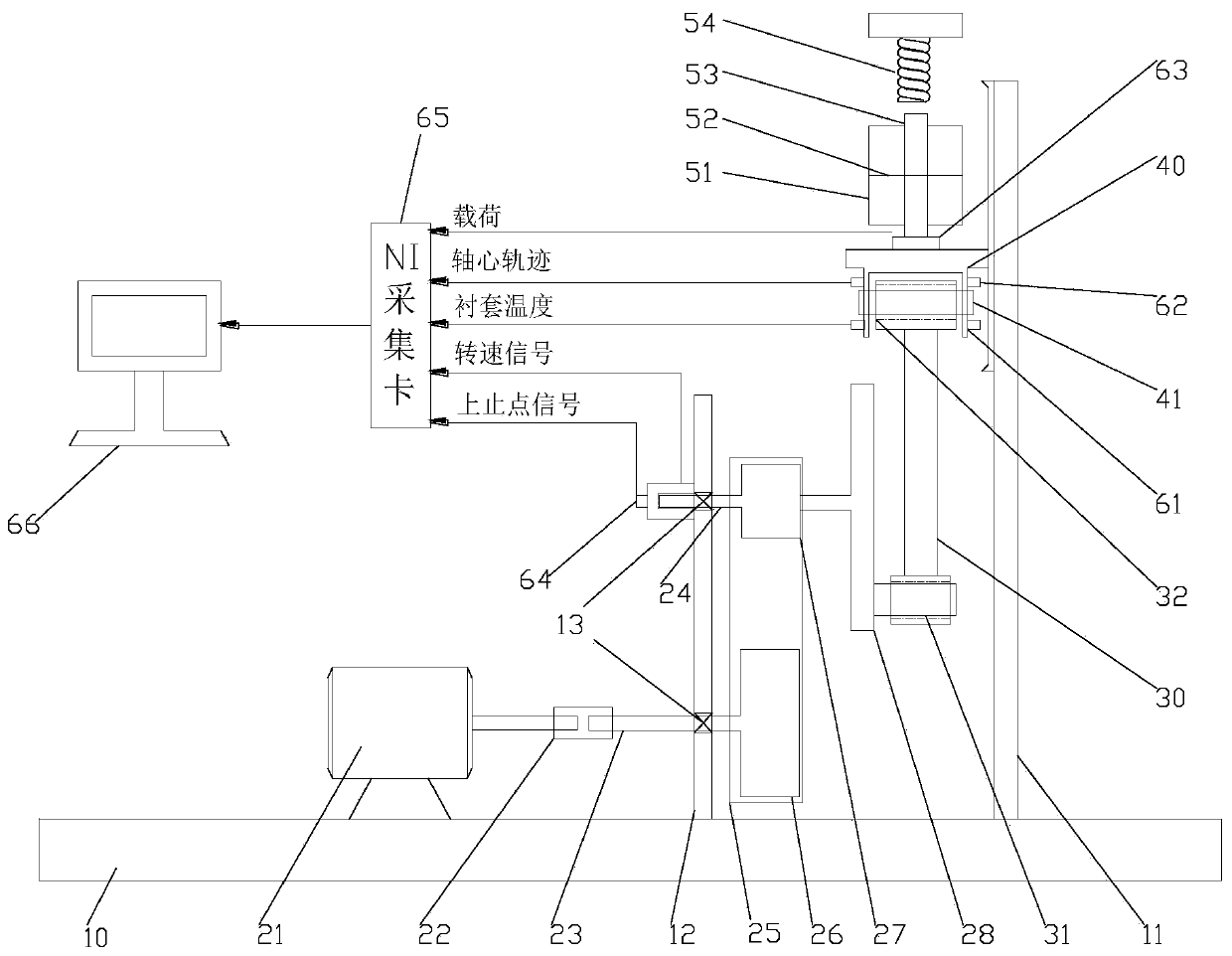
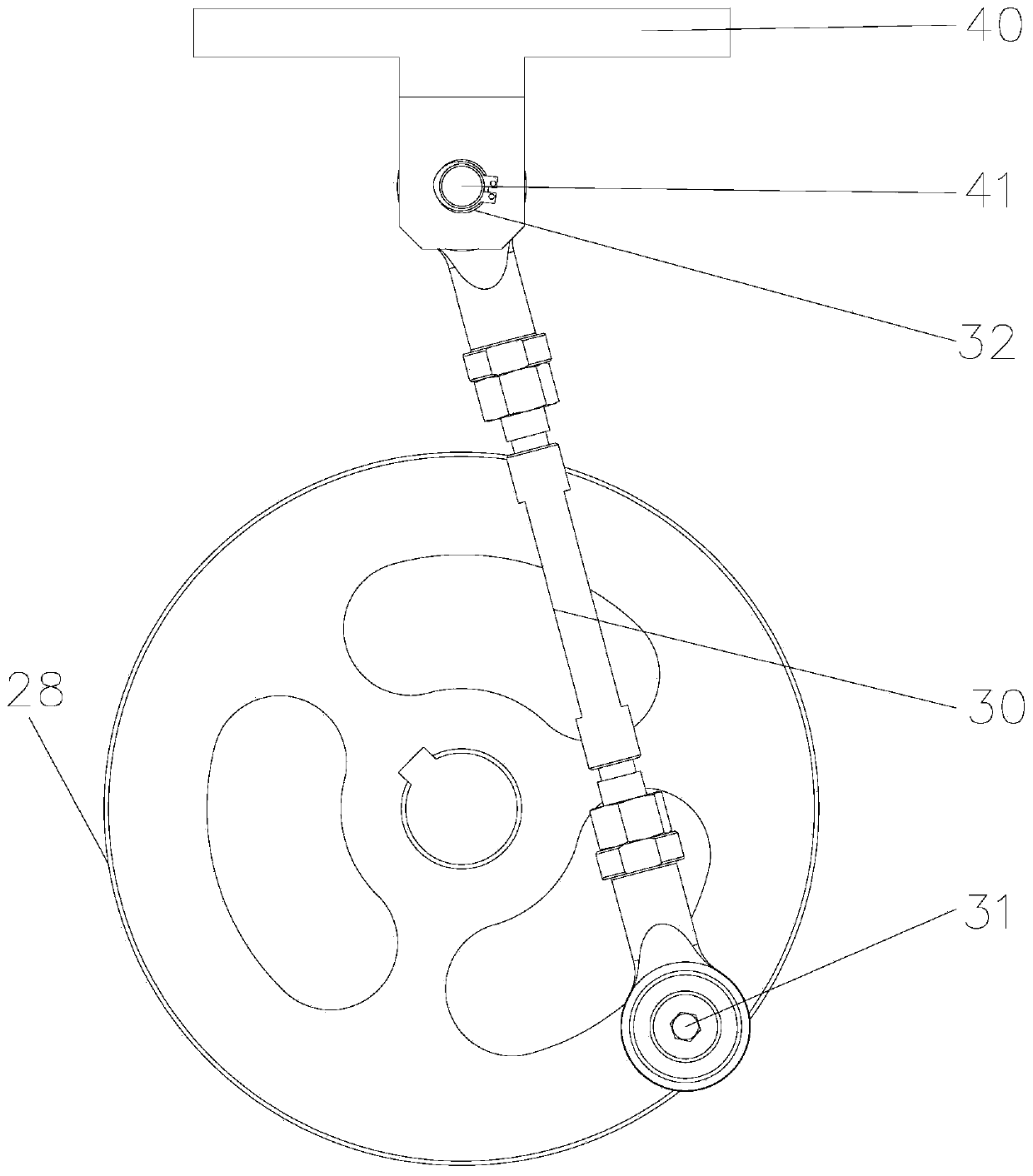
The invention relates to a marine engine connection rod bush wear simulation test device comprising a substrate, a vertical guide rail, a piston, a driving device, a connection rod and a loading device; the vertical guide rail is installed on the substrate; the piston is movably installed on the vertical guide rail; the driving device comprises a motor and an eccentric wheel, and the motor drivesthe eccentric wheel to rotate; the big end of the connection rod is hinged to the eccentric wheel via a pin roll, a connection rod bush is embedded into the small end of the connection rod, and a piston pin is inserted into the connection rod bush and in fit cooperation with the connection rod bush; and the loading device comprises an equivalent load hydraulic cylinder for applying a constant loadto the piston and a spring mechanism for applying an impact load to the piston. According to the device and method provided by the invention, the platform simulation tests can be performed on the piston pin-connection rod bush friction pair with the bushes made from different materials and subjected to different surface treatment, so that the wear abrasion characteristics of the bushes made fromthe different materials; and through measuring the track of the axis of the piston pin, the influences of the working condition parameters, structural parameters and technical methods of the simulation engine on the thickness of the oil film on the piston pin-connection rod bush friction pair can be acquired.
Description
technical field [0001] The invention relates to the technical field of marine engine simulation tests, in particular to a marine engine connecting rod bushing wear simulation test device and test method. Background technique [0002] The connecting rod bushing is one of the key parts of the marine engine. It connects the piston and the connecting rod through the piston pin and is used to support the piston pin. During the working process, the connecting rod bushing is affected by the periodically changing gas force and inertial force, and it is difficult to form a sufficient lubricating oil film. The harsh working environment makes the connecting rod bushing prone to wear and tear, resulting in blockage of the oil hole, which in turn leads to vicious accidents. Therefore, it is of great significance to study the friction and wear characteristics of the engine connecting rod bushing, and the test device is a necessary condition for the research of the connecting rod bushing. ...
Claims
Login to View More Application Information
Patent Timeline
 IPC IPC(8): G01M15/00G01M13/00
CPCG01M13/00G01M15/00
Inventor 杨建国万标郭阳
Owner WUHAN UNIV OF TECH
Features
- R&D
- Intellectual Property
- Life Sciences
- Materials
- Tech Scout
- Unparalleled Data Quality
- Higher Quality Content
- 60% Fewer Hallucinations
Learn More Browse by: Latest US Patents, China's latest patents, Technical Efficacy Thesaurus, Application Domain, Technology Topic, Popular Technical Reports.
© 2025 PatSnap. All rights reserved.Legal|Privacy policy|Modern Slavery Act Transparency Statement|Sitemap|About US| Contact US: help@patsnap.com


