Detection system and method for in-vitro diagnostic instrument

An in-vitro diagnosis and detection system technology, applied in instruments, biological tests, material inspection products, etc., can solve problems such as large size and inconvenient operation, achieve high test speed, convenient maintenance and repair, and avoid conflicts of use.

Active Publication Date: 2019-09-06
SHENZHEN YHLO BIOTECH
View PDF11 Cites 0 Cited by
  • Summary
  • Abstract
  • Description
  • Claims
  • Application Information

AI Technical Summary

Problems solved by technology

Cascaded analyzers are generally large in size, and some analyzers are far away from the terminal. For example, when one of the instruments is overhauled, the maintenance operator needs to observe and send control instructions at the control terminal, and then connect the control terminal and an analyzer. It is very inconvenient to move back and forth between

Method used


Image

  • Detection system and method for in-vitro diagnostic instrument
  • Detection system and method for in-vitro diagnostic instrument
  • Detection system and method for in-vitro diagnostic instrument

Examples


Embodiment Construction

[0028] In order to facilitate the understanding of the present application, the present application will be described more fully below with reference to the relevant drawings. Preferred embodiments of the application are shown in the accompanying drawings. However, the present application can be embodied in many different forms and is not limited to the embodiments described herein. On the contrary, the purpose of providing these embodiments is to make the disclosure of the application more thorough and comprehensive.

[0029] It should be noted that when an element is referred to as being “fixed” to another element, it can be directly on the other element or there can also be an intervening element. When an element is referred to as being "connected to" another element, it can be directly connected to the other element or intervening elements may also be present. The terms "vertical," "horizontal," "left," "right," and similar expressions are used herein for purposes of ill...


PUM


Abstract

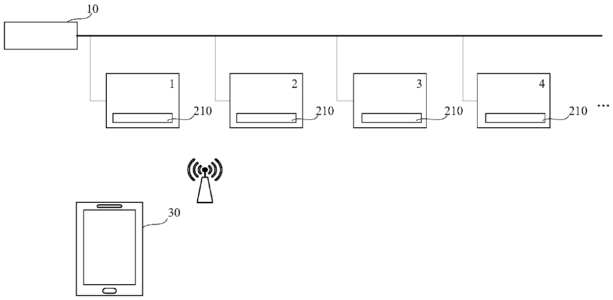
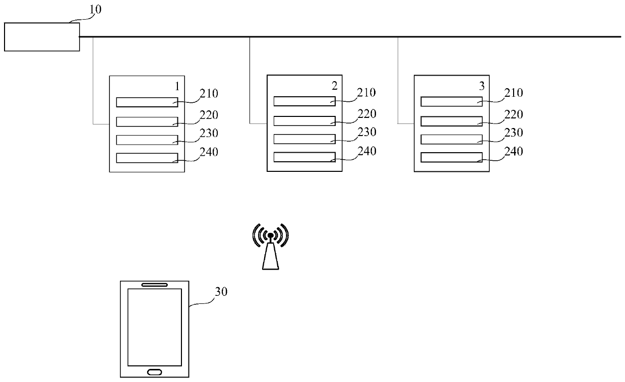
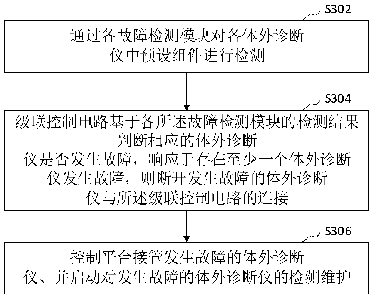
The present invention relates to a detection system and method for an in-vitro diagnostic instrument. The detection system of the in-vitro diagnostic instrument comprises a plurality of cascaded in-vitro diagnostic units, a cascaded control circuit and a control platform. The control platform and each in-vitro diagnostic unit are in a communication connection; the cascaded control circuit is connected with each in-vitro diagnostic unit; each in-vitro diagnostic unit includes a fault detection module; and each fault detection module is used to detect preset components in the corresponding in-vitro diagnostic unit. The cascaded control circuit determines whether the corresponding in-vitro diagnostic unit is faulty based on the detection result of each fault detection module, is responsive tothe presence of at least one faulty in-vitro diagnostic instrument and can disconnect from the faulty in-vitro diagnostic instrument. The control platform takes over the faulty in-vitro diagnostic instrument and activates the detection and maintenance of the faulty in-vitro diagnostic instrument. The application can prevent an operator from moving back and forth between a control terminal and a singe instrument, and provides great convenience for the maintenance and repair of the operator.

Description

technical field [0001] The invention relates to the field of medical testing equipment, in particular to a testing system and method for an in vitro diagnostic instrument. Background technique [0002] With the increase of testing traffic in the field of medical testing equipment, an analyzer with a higher testing speed is required. However, limited by the speed of a single analyzer, multiple analyzers have been developed for cascade use. Considering the convenience of operation, etc., this cascaded analyzer will have a unified control terminal (computer), and the test of the analyzer will be started on the unified control terminal, and the test results will be given. Cascaded analyzers are generally large in size, and some analyzers are far away from the terminal. For example, when one of the instruments is overhauled, the maintenance operator needs to observe and send control instructions at the control terminal, and then connect the control terminal and an analyzer. Wal...

Claims


Application Information

Patent Timeline
Patent Type & Authority Applications(China)
IPC IPC(8): G01N35/00G01N33/48
CPCG01N35/00594G01N33/48
Inventor 张福星肖育劲胡鹍辉
Owner SHENZHEN YHLO BIOTECH
Why Eureka
Try Eureka