
A multi-energy system operation scheduling method

A technology for operation scheduling and power system scheduling, applied in the field of multi-energy systems, can solve problems such as asynchronous decision-making, failure to protect information privacy of multi-energy systems, inconsistent scheduling goals of sub-energy systems, etc.

Active Publication Date: 2020-11-06
NARI TECH CO LTD +1
View PDF11 Cites 0 Cited by
  • Summary
  • Abstract
  • Description
  • Claims
  • Application Information

AI Technical Summary

Problems solved by technology

This method guarantees the optimality of scheduling decisions from a global perspective, but it still faces many difficulties in actual operation, such as failing to protect the information privacy of multi-energy systems, inconsistent scheduling goals and out-of-synchronization of decision-making among sub-energy systems.

Method used


Image

  • A multi-energy system operation scheduling method
  • A multi-energy system operation scheduling method
  • A multi-energy system operation scheduling method

Examples


Embodiment Construction

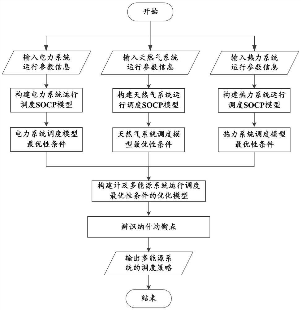
[0061] This embodiment provides a multi-energy system operation scheduling method, such as figure 1 shown, including the following steps:

[0062] Step 1: Construct the power system operation scheduling model in the multi-energy system.

[0063] Among them, the power system operation scheduling model adopts the form of second-order cone (SOC), specifically:

[0064]

[0065]

[0066]

[0067]

[0068]

[0069]

[0070]

[0071]

[0072]

[0073] In the formula: the subscripts i, j and l represent the nodes of the power system, the subscript c represents the CHP system, the superscripts max and min refer to the upper and lower limits of variables, respectively, P G with Q G Respectively refer to the active power and reactive power injected by the power supply, P L with Q L Respectively refer to the active power and reactive power of the load, C G refers to the power supply cost, F CHP,c Refers to the amount of natural gas consumed by CHP units i...


PUM


Abstract

The invention discloses an operation scheduling method for a multi-energy system, which includes: respectively constructing the operation scheduling model of the electric power system, the operation scheduling model of the natural gas system, and the operation scheduling model of the thermal system in the multi-energy system; solving the scheduling model of the power system and the scheduling model of the natural gas system respectively Optimal conditions of the model and thermal system scheduling model; construct the operation scheduling objective optimization function of the multi-energy system, and use the optimality condition obtained as a constraint; solve the objective optimization function, and obtain the Nash equilibrium of the non-cooperative game of the multi-energy system point; the power system, natural gas system, and thermal system in the multi-energy system are scheduled according to the scheduling strategy corresponding to the Nash equilibrium point. The invention can realize optimal operation scheduling.

Description

technical field [0001] The invention relates to multi-energy system technology, in particular to an operation scheduling method for a multi-energy system. Background technique [0002] Combined heat and power (CHP) has high energy conversion efficiency and has been widely used in power systems (especially power distribution systems) in recent years. CHP uses natural gas as fuel and simultaneously produces electrical power and thermal power. Therefore, CHP acts as a power source and a heat source in the power system and thermal system respectively, and is equivalent to a gas load in a natural gas system, and gradually deepens the coupling between multi-energy systems. [0003] The traditional planning and operation of electricity, natural gas, and thermal systems are independent. In the context of the gradual deepening of coupling between sub-energy systems, independent operation scheduling is not economically strict and optimal, and may even easily cause hidden dangers in t...

Claims


Application Information

Patent Timeline
Patent Type & Authority Patents(China)
IPC IPC(8): G06F30/20G06Q10/04G06Q50/06H02J3/46
CPCG06Q10/04G06Q50/06H02J3/46G06F30/20H02J2203/20Y02E40/70Y04S10/50
Inventor 滕贤亮杜刚吴仕强陈胜卫志农孙国强臧海祥王文学
Owner NARI TECH CO LTD
Learn More