Supercharge Your Innovation With Domain-Expert AI Agents!

A connector assembly and a connector for conveniently identifying when a connecting nut is assembled in place

A technology of connector components and connecting nuts, which is applied to parts of connecting devices, devices for preventing wrong connections, devices for engaging/disconnecting connected parts, etc., which can solve the problem of insufficient contrast, poor assembly accuracy, and connection problems. The assembly accuracy of device components is not guaranteed, and the effect of ensuring assembly accuracy and convenient touch is achieved.

Active Publication Date: 2020-09-18
CHINA AVIATION OPTICAL-ELECTRICAL TECH CO LTD
View PDF4 Cites 0 Cited by
  • Summary
  • Abstract
  • Description
  • Claims
  • Application Information

AI Technical Summary

Problems solved by technology

[0005] The purpose of the present invention is to provide a connector assembly that is convenient for identifying when the connecting nut is assembled in place, so as to solve the problem that in the prior art, the contrast is not obvious enough in the way of identifying that the connecting nut is assembled in place by using a groove in place on the corresponding connector housing 1. The technical problem that the assembly accuracy is not guaranteed; at the same time, the purpose of the present invention is to provide a connector that is easy to identify when the connecting nut is assembled in place, so as to solve the problem of using the corresponding connector housing to set the groove in place in the prior art. Identify the technical problem that the assembly accuracy of the connector assembly is not guaranteed due to the way the connecting nut is assembled in place

Method used


Image

  • A connector assembly and a connector for conveniently identifying when a connecting nut is assembled in place
  • A connector assembly and a connector for conveniently identifying when a connecting nut is assembled in place
  • A connector assembly and a connector for conveniently identifying when a connecting nut is assembled in place

Examples


Embodiment Construction

[0022] The embodiments of the present invention will be further described below in conjunction with the drawings.

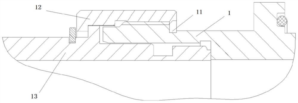
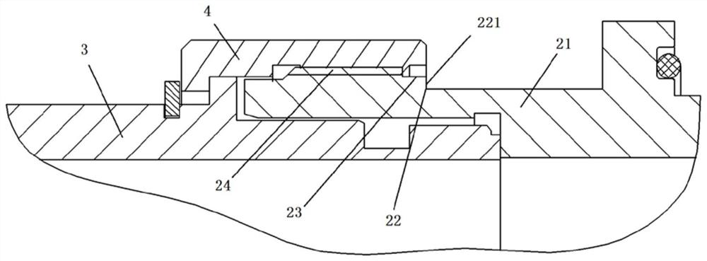
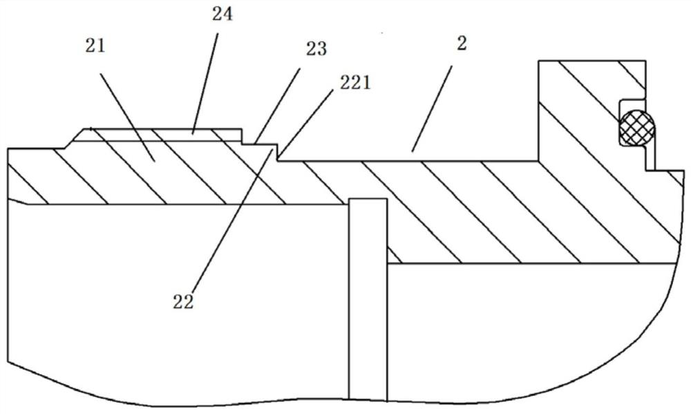
[0023] Specific embodiments of the connector assembly of the present invention, such as figure 2 As shown, the connector assembly includes a connector 2, an adapter connector 3, and a connecting nut 4. The connector 2 and the adapter connector 3 are mated and fitted. The outer circumference of the connector 2 is provided with an external thread section 24. The connecting nut 4 can be rotated and preset on the adapter connector 3 to define the connecting nut. 4 The end close to the in-position step 22 is the back end, the adapter connector 3 is provided with a convex circle, the front end of the connecting nut 4 is provided with a flange, and the flange of the connecting nut 4 is the same as the convex circle on the adapter connector 3. The stop fit is used to restrict the connection nut 4 from falling out of the adapter connector 3 backwards. A ring groove is prov...


PUM


Abstract

The invention relates to a connector assembly and a connector convenient for identifying in-place assembling of a connection screw cap. The connector assembly convenient for identifying in-place assembling of the connection screw cap comprises a connector and an adapter connector which are adaptably plugged and the connection screw cap which sleeve the connector and the adapter connector so as tofasten the connector and the adapter connector. The connector comprises a connector shell. The periphery of the connector shell is provided with an externally threaded section which is connected withthe connection screw cap through threads. The end of the connector plugged with the adapter connector is defined as a front end. An in-place step is arranged on the rear part of the externally threaded section on the connector shell. The in-place step is provided with a step surface which is used for manual touch by an operator when tightening the connection screw cap to indicate in-place assembling of the connection screw cap when being leveled with the rear end surface of the connection screw cap. The step surface is arranged in a protruding way, the step surface of the in-place step is leveled with the rear end surface of the connection screw cap in case of in-place assembling of the connection screw cap and operator touch can be facilitated.

Description

Technical field [0001] The invention relates to a connector assembly and a connector which are convenient for identifying the assembly of a connecting nut. Background technique [0002] With the continuous progress of the electronics industry, electronic devices are developing towards miniaturization and integration, and connectors play a very important role as an interface for signal transfer and transmission of electronic devices. The Chinese utility model patent with the authorized announcement number CN205828758U and the authorized announcement date of 2016.12.21 discloses a flameproof connector. The flameproof connector includes a socket, a plug and a connecting nut. The plug and the socket are locked by the connecting nut. fixed. The plug and socket of the connector must be assembled in place, and the contact in the plug must be in good contact with the contact in the socket to ensure the circuit conduction. For this reason, it becomes very important whether the connectin...

Claims


Application Information

Patent Timeline
Patent Type & Authority Patents(China)
IPC IPC(8): H01R13/641H01R13/622
CPCH01R13/622H01R13/641
Inventor 苏雯
Owner CHINA AVIATION OPTICAL-ELECTRICAL TECH CO LTD
Features
  • R&D
  • Intellectual Property
  • Life Sciences
  • Materials
  • Tech Scout
  • Unparalleled Data Quality
  • Higher Quality Content
  • 60% Fewer Hallucinations
Learn More