
Overall assembling method for ultra-wide framing steel box girder

A technology of steel box girder and ultra-wide division, which is applied in bridges, bridge materials, bridge construction, etc., can solve the problems of low construction efficiency, long erection period, and difficulty in high-altitude operation, so as to reduce the amount of welds and shorten the manufacturing cycle. Effect

Inactive Publication Date: 2020-11-13
中铁山桥(南通)有限公司
View PDF6 Cites 15 Cited by
  • Summary
  • Abstract
  • Description
  • Claims
  • Application Information

AI Technical Summary

Problems solved by technology

[0004] However, this assembly method will lead to a long manufacturing cycle of the steel box girder, and the external dimensions are not easy to control, and the "long-line method" assembly scheme that is completed by multi-segment continuous matching manufacturing and pre-assembly at the same time, the shrinkage of the welding ring seam and the cable force It is difficult to correct the effect of the compression of the beam section on the length caused by it. The correction is difficult, which affects the assembly accuracy of the steel box girder, and it is difficult to control the assembly quality. It is directly erected after pre-assembly. When erecting, it is found that the beam section size is wrong or the pre-camber If it does not match, it needs to be adjusted at high altitude. It is difficult to work at high altitude, the erection period is long, and the construction efficiency is low.

Method used


Image

  • Overall assembling method for ultra-wide framing steel box girder
  • Overall assembling method for ultra-wide framing steel box girder
  • Overall assembling method for ultra-wide framing steel box girder

Examples


Embodiment Construction

[0049] The present invention will be described in further detail below in conjunction with the accompanying drawings.

[0050] In order to make the object, technical solution and advantages of the present invention clearer, the present invention will be further described in detail below in conjunction with the accompanying drawings and specific embodiments. The following examples can enable those skilled in the art to understand the present invention more comprehensively, but the present invention is not limited to the scope of the described examples.

[0051] This specific implementation mode adopts the following technical scheme: including plate unit manufacturing, plate assembly welding, beam segment matching assembly welding, pre-assembly, pre-assembly inspection, pre-assembly and assembly welding are completed at one time, and the specific steps are as follows:

[0052] S1. Plate unit manufacturing and plate assembly welding:

[0053] S1.1. After the steel plate is sampl...


PUM


Abstract

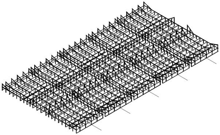
The invention discloses an overall assembling method for an ultra-wide framing steel box girder, and relates to the technical field of steel box girder assembling. The method comprises the steps performing plate unit manufacturing and plate assembly welding, beam section matching assembly welding and pre-assembling and pre-assembling inspection; carrying out beam section assembly welding accordingto the sequence of a bottom plate, a transverse partition plate, a middle top plate, a primary positioning inner web plate, an anchor web plate, other top plates, a secondary positioning anchor web plate, a middle cross beam and a cantilever arm block, and carrying out three-dimensional stepped propelling mode section-by-section assembly and welding; and during pre-assembling, with considerationof the influence of beam section compression amount caused by welding circular seam shrinkage amount and cable force on the length, correcting the accumulated total length and error of the previous pre-assembling in the next assembly. The method has the advantages that the butt joint weld joint amount of the steel box girder on the total assembly jig frame can be reduced, and the manufacturing period is shortened; a three-dimensional step-shaped propelling mode is adopted, pre-assembling is carried out after section-by-section assembly welding, and the boundary dimension is easy to control; the assembling precision of the steel box girder can be ensured, the assembling quality is controlled, high-altitude adjustment is avoided, and the erection period is shortened.

Description

technical field [0001] The invention relates to the technical field of steel box girder assembling, in particular to an overall assembling method of an ultra-wide framed steel box girder. Background technique [0002] Steel box girder, also known as steel plate box girder, is a commonly used structural form of long-span bridges. In long-span cable-supported bridges, the steel box girder spans hundreds of meters to thousands of meters, and is generally divided into several beam sections for manufacture and installation. Its cross section has wide and flat shape characteristics, and its aspect ratio reaches 1 : Around 10. The steel box girder is generally connected by the top plate, bottom plate, web plate, transverse diaphragm, longitudinal diaphragm and stiffener through all welding. [0003] In the prior art, an ultra-wide steel box girder horizontal multi-segment division and assembly method with the application number 201811603613.9 is disclosed, which adopts two proces...

Claims


Application Information

Patent Timeline
IPC IPC(8): E01D21/00E01D2/04E01D101/30
CPCE01D2/04E01D21/00E01D2101/30
Inventor 马浩鹏张平薛军聂立恒李维张蓝鹏黄东东贾秀峰杨瑞瑞
Owner 中铁山桥(南通)有限公司
Learn More