Separator plate installation cavity structure for electrical power distribution cabinet

A power distribution cabinet and partition technology, which is applied in the field of partition installation chamber structure, can solve the problems of low space utilization rate and cluttered wiring, and achieve the effect of reducing fetters, simple structure and reducing wrong connection.

Inactive Publication Date: 2019-09-06
郑江恋
View PDF5 Cites 2 Cited by
  • Summary
  • Abstract
  • Description
  • Claims
  • Application Information

AI Technical Summary

Problems solved by technology

[0005] In order to solve the above technical problems, the present invention provides a partition installation chamber structure used in the electrical distribution cabinet to solve the existing problems of no space division, messy wiring and low space utilization

Method used


Image

  • Separator plate installation cavity structure for electrical power distribution cabinet
  • Separator plate installation cavity structure for electrical power distribution cabinet
  • Separator plate installation cavity structure for electrical power distribution cabinet

Examples


Embodiment

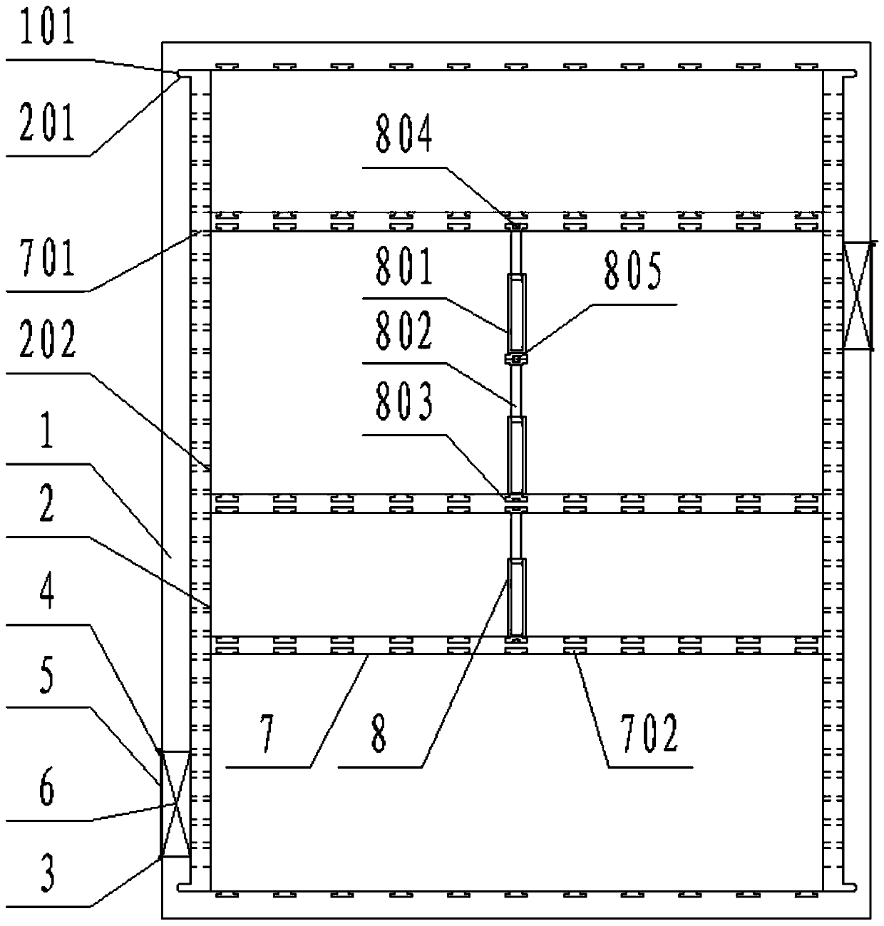
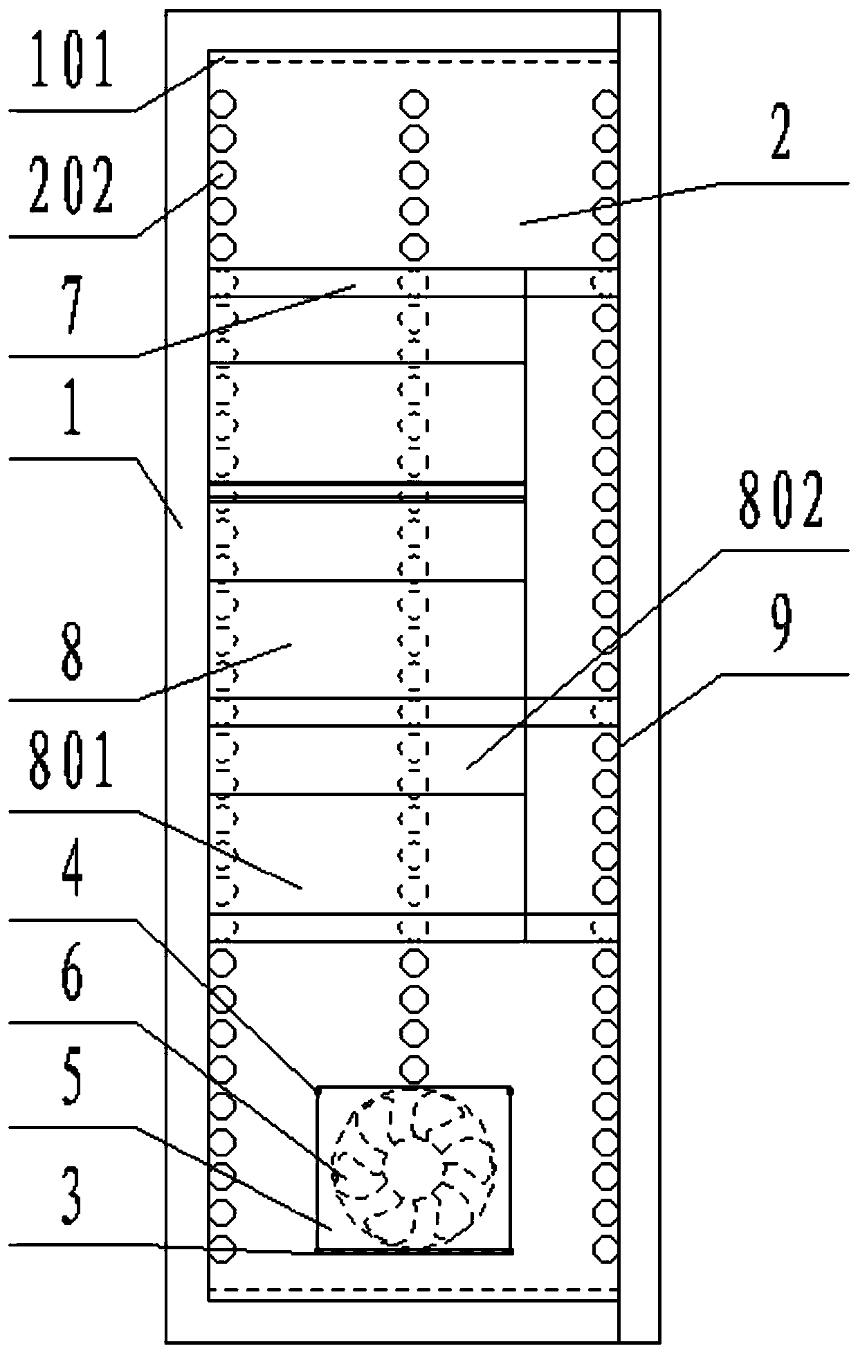
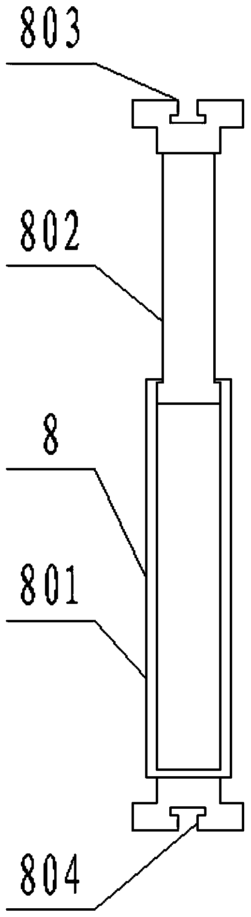
[0033] As attached figure 1 Attached Figure 8 Shown: a partition installation chamber structure used in electrical power distribution cabinets, including cabinet body 1, side slot 101, side plate 2, side strip 201, jack 202, slot 3, protective hook 4, filter Net 5, fan 6, partition 7, pin 701, T-slot 702, riser 8, outer panel 801, inner panel 802, T-shaped strip 803, connecting groove 804, connecting strip 805 and front door 9; the cabinet 1 is a box structure with an opening at the front; there are four side grooves 101, which are opened above and below the left and right inner walls of the cabinet 1; the socket 202 is a circular through hole, which is opened on the side plate 2. There are three rows, and the jacks 202 on each row are equally spaced; there are two slots 3, welded on the left and right side walls of the cabinet 1, the left side is on the bottom, and the right side is on the top; the protective hook 4 is The L-shaped bending plate is welded on the left and rig...


PUM


Abstract

The invention provides a separator plate installation cavity structure for an electrical power distribution cabinet. The structure comprises a connecting slot, a connecting strip and a front door. Insert holes are circular through holes, and are arranged in side plates; the insert holes are arranged in three rows; and the insert holes in each row are equally spaced. Protection hooks are L-shaped bending plates, are welded to the left and right sides of a cabinet body and are arranged above slots. Two opening-opposite protection hooks are arranged above each slot. Two fans are embedded in the left and right walls of the cabinet body respectively, and are within the shielding range of a filter screen. The front door is connected to the front side surface of the cabinet body. The separator plate installation cavity structure is simple in structure, can divide the space inside the cabinet freely, can change freely according to the size of electrical components, and can make full use of theinternal space to separate the components, thereby reducing fetters during maintenance and repairing, increasing safety of maintenance and repairing and reducing the phenomenon of misconnection during line maintenance; and the structure has good ventilation, thereby preventing internal heat storage.

Description

Technical field [0001] The invention belongs to the technical field of power distribution cabinets, and more specifically, relates to a partition installation chamber structure used in an electrical power distribution cabinet. Background technique [0002] The power distribution cabinet is used to place the boxes of voltage appliances, collectively called the power distribution center. They are centrally installed in the enterprise's substations and distribute the electric energy to lower-level power distribution equipment in different locations. [0003] Based on the above, the inventor found that the existing power distribution cabinet has many electrical components and is not partitioned. Only one or two partitions are used to divide the space. The wiring is messy, the maintenance is inconvenient, and it is easy to encounter other The connection line of the fixed partition is prone to waste of space utilization, and the phenomenon that the volume of electrical components does n...

Claims


Application Information

Patent Timeline
Patent Type & Authority Applications(China)
IPC IPC(8): H02B1/30
CPCH02B1/30
Inventor 郑江恋
Owner 郑江恋
Why Eureka
Try Eureka