Inserting box with drawing box

A technology for inserting boxes and boxes, which is applied in the direction of clamping/extracting devices and supporting structure installation, which can solve the problems of occupying the inner space of the inserting box and the small storage space of the drawer box, and achieve simplified structure, easy installation, and product cost saving Effect

Active Publication Date: 2019-09-06
CHINA AVIATION OPTICAL-ELECTRICAL TECH CO LTD
View PDF10 Cites 0 Cited by
  • Summary
  • Abstract
  • Description
  • Claims
  • Application Information

AI Technical Summary

Problems solved by technology

[0004] The invention provides a box with a drawer, which is used to solve the problem that the existing guiding structure occupies the inner space of the box, so that the storage space of the drawer is small

Method used


Image

  • Inserting box with drawing box
  • Inserting box with drawing box
  • Inserting box with drawing box

Examples


Embodiment Construction

[0032] The specific embodiments of the present invention will be further described below in conjunction with the accompanying drawings.

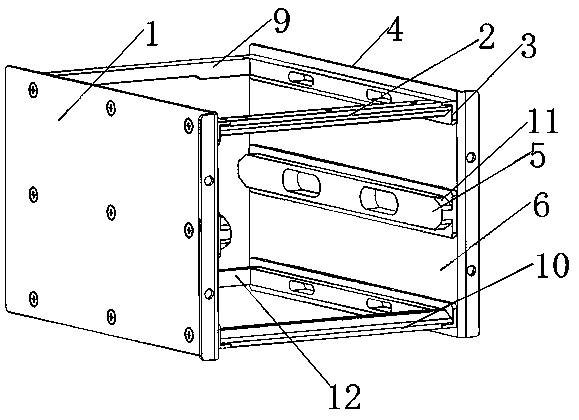
[0033] Embodiments of the plug box with drawer of the present invention, such as Figure 3~Figure 7 As shown, it includes the box body and the two-layer drawer placed inside the box.

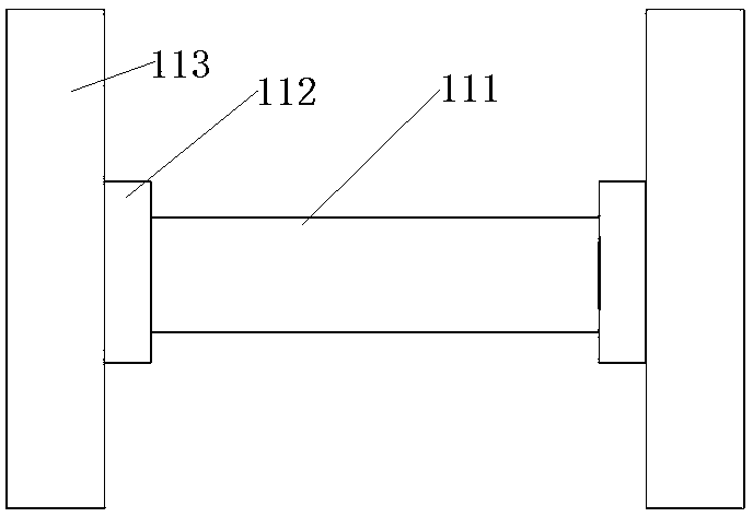
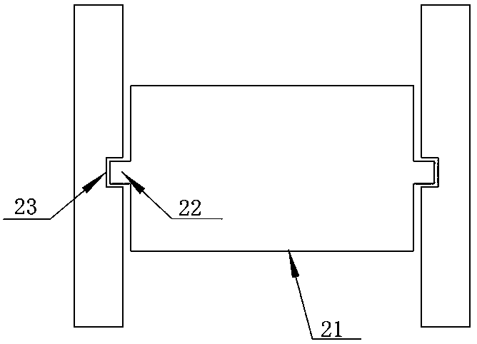
[0034] The box body includes a left panel 1 and a right panel 4, such as image 3 As shown, the left side plate 1 and the right side plate 4 form the left and right side walls of the box body, and the left side plate 1 and the right side plate 4 form the outer frame of the box body through the cross beam and the tail beam erected between the two side plates , the front end of the external frame is the entrance for pushing the drawer 7 into the box, the rear end of the external frame is the tail for inserting the drawer 7 into the corresponding socket (not shown in the figure), at the entrance The upper and lower beams are connected by screws, and the upper a...


PUM


Abstract

The invention relates to the field of inserting boxes, and particularly relates to an inserting box with a drawing box. The inserting box comprises a box body and the drawing box arranged in the box body. The box body is internally provided with a guide support structure which is used for guiding the drawing box. The two oppositely arranged side walls of the box body are respectively provided witha guide recess. The two corresponding sides of the drawing box body are assembled in the two guide recesses respectively in a guide way. The guide support structure is formed by the guide recesses. The drawing box acts as a part of a guided and pushed guide mechanism without additional arrangement of a guide structure occupying the space of the inserting box on the drawing box so as to reserve the installing space of the drawing box and save the product cost.

Description

technical field [0001] The invention relates to the field of box insertion; in particular, it relates to a box insertion with a drawer. Background technique [0002] With the development of modularization and miniaturization of various electronic equipment, subracks have been widely used in electronic equipment cabinets. The integrated frame installed in subracks is generally horizontally loaded with several drawers along the up and down directions. There is a plug at the back of the drawer, which is mated with the socket on the back panel of the box to realize electrical connection. In order to achieve accurate mating, the drawer generally has a guiding mechanism when it is pushed in. [0003] There are two common guiding mechanisms in the prior art, such as figure 1 and figure 2 as shown, figure 1 The plug-in box in the box adopts the slide rail 112 installed on the side wall 113 of the plug-in box, and the slide rail 112 is also installed on both sides of the drawer 1...

Claims


Application Information

Patent Timeline
Patent Type & Authority Applications(China)
IPC IPC(8): H05K7/14
CPCH05K7/1411
Inventor 翟新星
Owner CHINA AVIATION OPTICAL-ELECTRICAL TECH CO LTD
Why Eureka
Try Eureka