Forming operating mechanism for steel reinforcement cage with protecting layers and method

A forming operation and steel cage technology, applied in the direction of structural elements, building components, building structures, etc., can solve the problems of consuming manpower and material resources, unreliable spacing between main bars, and complicated position calibration

Active Publication Date: 2019-09-10
SCEGC NO 5 CONSTRUCTION ENGINEERING GROUP COMPANYLTD
View PDF7 Cites 2 Cited by
  • Summary
  • Abstract
  • Description
  • Claims
  • Application Information

AI Technical Summary

Problems solved by technology

[0002] At present, the pile foundation is extremely critical in various construction projects, and the production quality and production efficiency of the pile foundation reinforcement cage are important factors affecting the construction quality and progress of the pile foundation. Composition, the reinforcement cage plays a very important role in the stability of the main project. At the present stage, in the process of on-site production of the reinforcement cage for construction, it is often faced with unreliable spacing between the main reinforcements, complicated position calibration, and large errors. Accurate arrangement is required, which will cause uneven stress and affect the later buildings. At the same time, when arranging the main reinforcement of the reinforcement cage, set the stirrups outside the main reinforcement of the reinforcement cage, and mark the stirrups with chalk

Method used


Image

  • Forming operating mechanism for steel reinforcement cage with protecting layers and method
  • Forming operating mechanism for steel reinforcement cage with protecting layers and method
  • Forming operating mechanism for steel reinforcement cage with protecting layers and method

Examples


Embodiment Construction

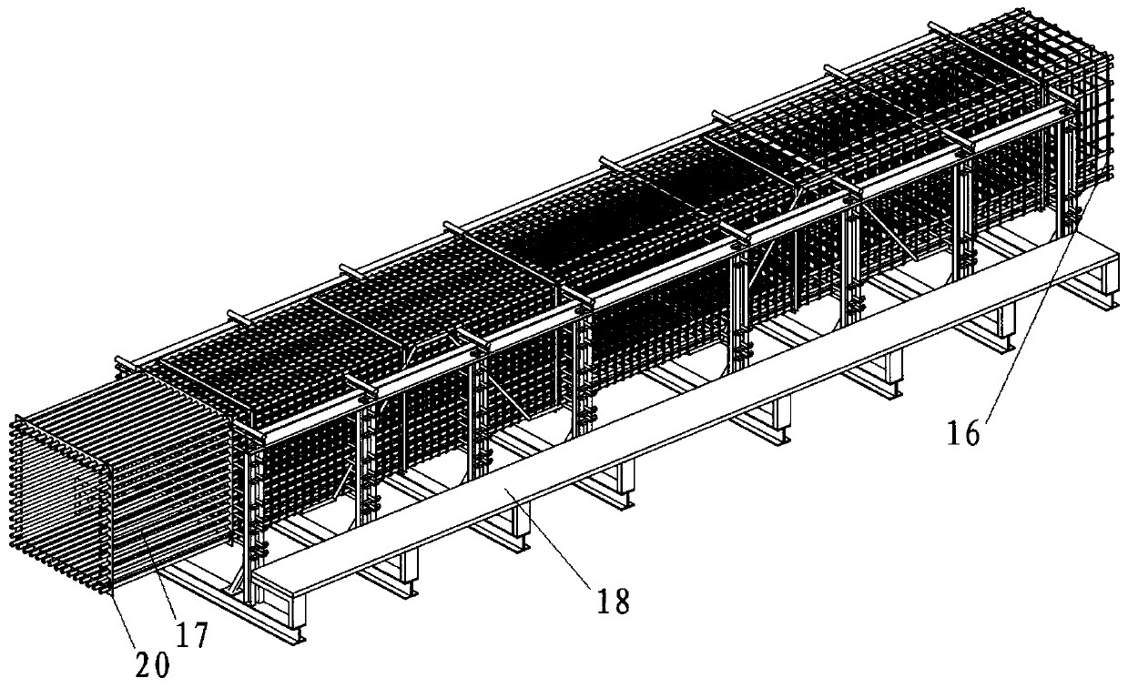
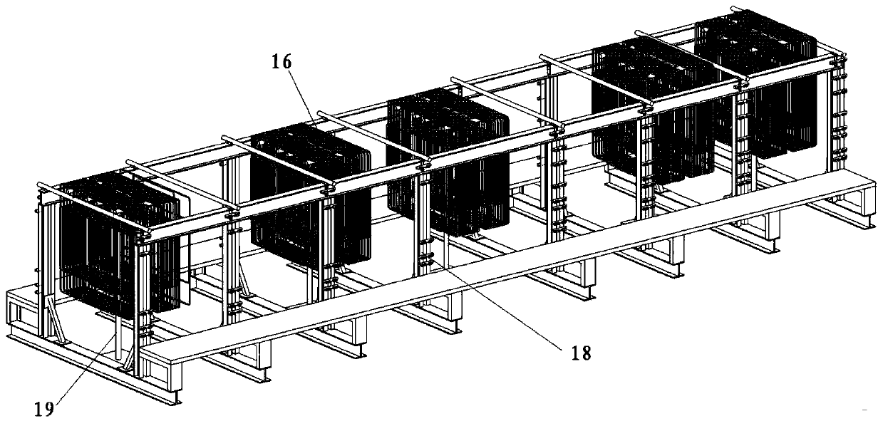
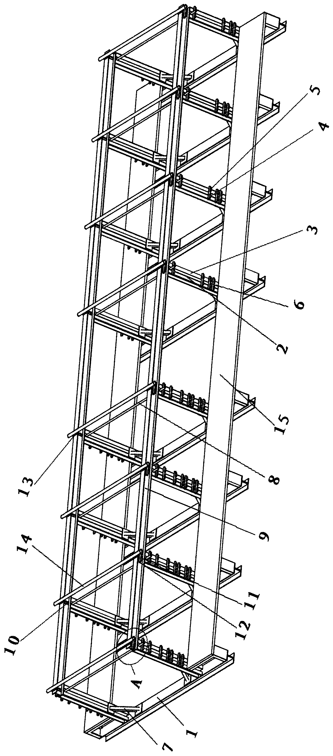
[0068] Such as Figure 1 to Figure 12 As shown, the present invention includes a main reinforcement positioning frame 18 for locating the position of the main reinforcement 17, a plurality of stirrup suspension frames 19 that are all matched with the main reinforcement positioning frame 18 and are used to support the suspension stirrup 16, and a plurality of sleeves along the length direction of the reinforcement cage. The protective layer 20 arranged outside the main reinforcement of the reinforcement cage, the main reinforcement positioning frame 18 includes two top supporting steel beams 9 arranged in parallel, and a plurality of top supporting steel beams 9 along the length direction of the top supporting steel beams 9 are arranged in parallel on the top of the two top supporting steel beams 9. The steel cage load-bearing bar 14 and a plurality of support positioning mechanisms arranged in parallel at the bottom of the two top support steel beams 9 along the length directio...


PUM


Abstract

The invention discloses a forming operating mechanism for a steel reinforcement cage with protecting layers and a method. The operating mechanism comprises a main reinforcement positioning frame usedfor positioning the positions of main reinforcements, multiple stirrup suspension brackets which cooperate with the main reinforcement positioning frame and are used for supporting suspension stirrupsand the multiple protecting layers which are arranged outside the steel reinforcement cage main reinforcements in a sleeving manner in the length direction of the steel reinforcement cage. The methodcomprises the steps of 1 arranging the stirrup suspension brackets, 2 suspending the stirrups, 3 inserting the first-layer main reinforcements, 4 moving the stirrups on the stirrup suspension brackets, 5 taking out the stirrup suspension brackets, 6 fixing the stirrups and the first-layer main reinforcements, 7 positioning and bundling the main reinforcements within the height range of top supporting steel beams, 8 positioning and bundling the remaining main reinforcements and 9 installing the protecting layers. According to the forming operating mechanism for the steel reinforcement cage with the protecting layers and the method, the stirrups can be easily supported and are skillfully matched with the first-layer main reinforcements, the positions of the main reinforcements are positioned through limiting of positioning rods and the stirrups, positioning rod supporting parts are extracted out to enable the positioning rods to fall down, and it is guaranteed that the spacing distanceamong the main reinforcements is invariable through installation of the protecting layers.

Description

technical field [0001] The invention belongs to the technical field of reinforcement cage forming, and in particular relates to a reinforcement cage forming operating mechanism and method with a protective layer. Background technique [0002] At present, the pile foundation is extremely critical in various construction projects, and the production quality and production efficiency of the pile foundation reinforcement cage are important factors affecting the construction quality and progress of the pile foundation. Composition, the reinforcement cage plays a very important role in the stability of the main project. At the present stage, in the process of on-site production of the reinforcement cage for construction, it is often faced with unreliable spacing between the main reinforcements, complicated position calibration, and large errors. Accurate arrangement is required, which will cause uneven stress and affect the later buildings. At the same time, when arranging the mai...

Claims


Application Information

Patent Timeline
IPC IPC(8): B21F27/20E04C5/06
CPCB21F27/20E04C5/0604
Inventor 罗睿唐超袁筑宇周鑫段明雷翟会军郭涛石涛王刚杨振密
Owner SCEGC NO 5 CONSTRUCTION ENGINEERING GROUP COMPANYLTD
Why Eureka
Try Eureka