Supercharge Your Innovation With Domain-Expert AI Agents!

Electric tool

A technology of electric tools and electricity, applied in the field of electric tools equipped with electric motors, can solve the problems of using belt grinders and the like

Active Publication Date: 2019-09-10
PANASONIC INTELLECTUAL PROPERTY MANAGEMENT CO LTD
View PDF6 Cites 3 Cited by
  • Summary
  • Abstract
  • Description
  • Claims
  • Application Information

AI Technical Summary

Problems solved by technology

Therefore it is difficult to suppress this vibration of the handle with the hand holding the handle
[0005] Also, in the case of a belt grinder, since the motor shaft of the motor is perpendicular to the length direction of the handle, the motor protrudes in the width (or lateral) direction of the handle
This makes it difficult to use a belt grinder in tight spaces, such as the inside of pipes in plumbing (e.g., electrical conduit or water pipes), because the motor becomes an obstacle

Method used


Image

  • Electric tool
  • Electric tool
  • Electric tool

Examples


Embodiment Construction

[0014] Hereinafter, embodiments of the present disclosure will be explained. The following embodiments are merely examples of various embodiments of the present disclosure. Various modifications to the following embodiments in view of the general arrangement and the like are possible as long as the purpose of the present disclosure is achieved. For convenience of explanation, forward (F), backward (B), left (L), right (R), upward (U) and downward (D) directions are used in the following explanation. However, it is not intended to limit the direction of use of the electric power tool according to this embodiment.

[0015] (Example)

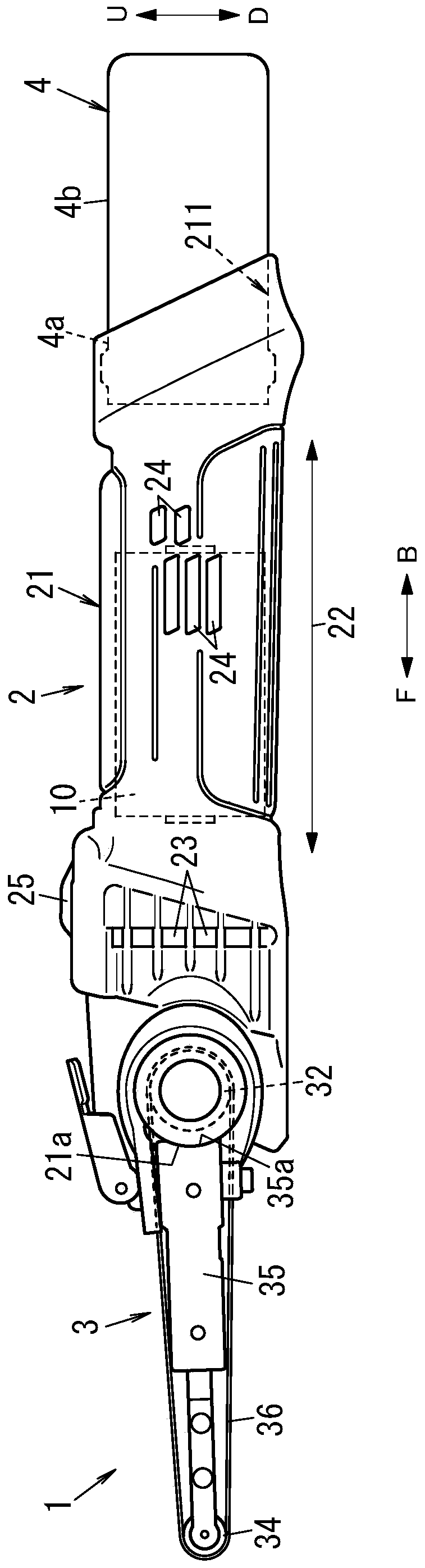
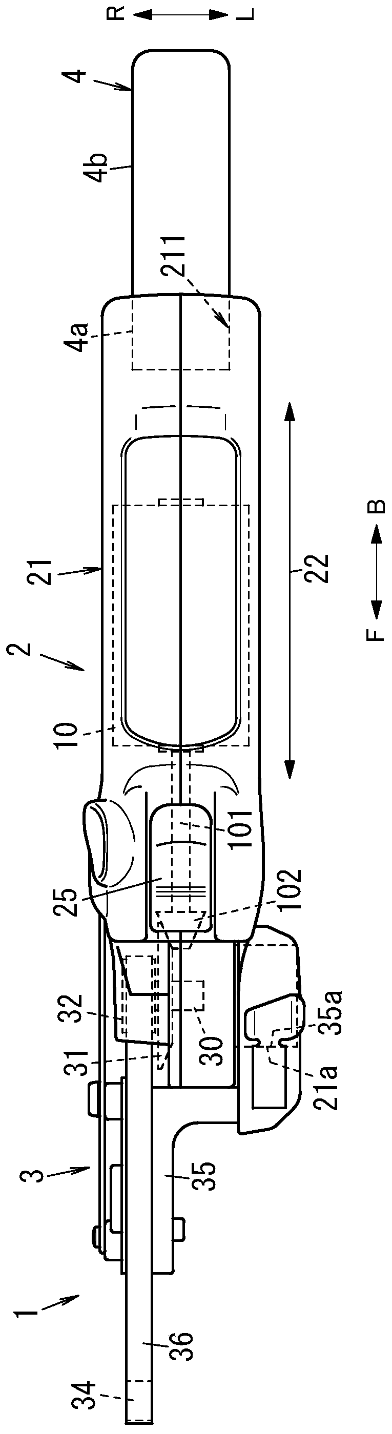
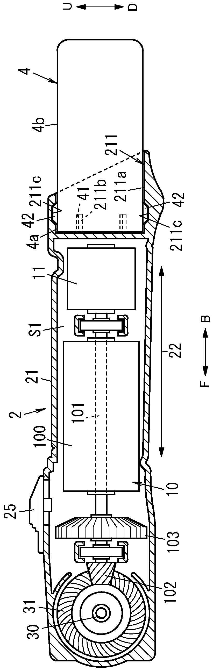
[0016] will refer to Figures 1A to 2B An electric tool (or power tool) 1 according to the present embodiment is explained.

[0017] like Figure 1A and 1B As shown, the power tool 1 is configured, for example, as a hand-held belt grinder. Such a belt grinder is a tool for grinding a target object by a polishing surface of an endless belt rot...


PUM


Abstract

The present invention provides an electric tool that enables user to easily suppress vibration of motor with hand and that is usable even in narrow spaces and outdoors. The electric tool (1) includesa grinding mechanism (3), a motor (10), a battery pack (4) and a housing (21). The motor (10) is configured to drive the grinding mechanism (3). The battery pack (4) is configured to supply the motor(10) with electric power. The grinding mechanism (3), the motor (10) and the battery pack (4) are fixed to the housing (21). The motor (10) possesses a rotary shaft (101) configured to transmit rotarydrive power to the grinding mechanism (3). The housing (21) possesses a handle (22) that allows user to hold. The grinding mechanism (3), the motor (10), the battery pack (4) and the handle (22) arearranged in one direction. The rotary shaft (101) of the motor (10) is elongated in the one direction.

Description

technical field [0001] The present disclosure relates generally to power tools, and more particularly, to a power tool equipped with an electric motor. Background technique [0002] Document 1 (JP2002-233942A) discloses a belt grinder as an example of an electric motor-equipped electric tool. The belt grinder described in Document 1 is equipped with a handle, a motor, a driving roller, an arm, a driven roller, and a grinding belt. The handle allows the user to hold. The motor is provided at the front end of the handle. The motor has a motor shaft perpendicular to the length direction of the handle. The drive roller is fixed to the motor shaft of the electric motor. The handle is provided with an arm protruding forward from the drive roller. The driven roller is provided at the front end portion of the arm so as to be allowed to rotate with the driven roller separated from the driving roller. A grinding belt loops around the drive and driven rolls. [0003] With a belt...

Claims


Application Information

Patent Timeline
IPC IPC(8): B24B23/06
CPCB24B23/06B25F5/02
Inventor 中村雅道
Owner PANASONIC INTELLECTUAL PROPERTY MANAGEMENT CO LTD
Features
  • R&D
  • Intellectual Property
  • Life Sciences
  • Materials
  • Tech Scout
  • Unparalleled Data Quality
  • Higher Quality Content
  • 60% Fewer Hallucinations
Learn More