
A method for measuring the output torque of a harmonic reducer flex wheel

A technology of harmonic reducer and output torque, applied in force/torque/work measuring instruments, measuring devices, torque measurement and other directions, which can solve the difficulty of accurately obtaining joint end torque, inaccurate indirect measurement, and complex joint force process, etc. problem, to achieve the effect of direct measurement and simple calculation

Active Publication Date: 2021-07-30
NANKAI UNIV
View PDF11 Cites 0 Cited by
  • Summary
  • Abstract
  • Description
  • Claims
  • Application Information

AI Technical Summary

Problems solved by technology

[0003] The present invention proposes a harmonic deceleration method to solve the problems in the existing robot force feedback control that it is difficult to accurately obtain the torque at the end of the joint, and the process of calculating the joint force by modeling the robot is complicated and the indirect measurement is inaccurate. Measuring method of output torque of flexible spline

Method used


Image

  • A method for measuring the output torque of a harmonic reducer flex wheel
  • A method for measuring the output torque of a harmonic reducer flex wheel
  • A method for measuring the output torque of a harmonic reducer flex wheel

Examples


Embodiment

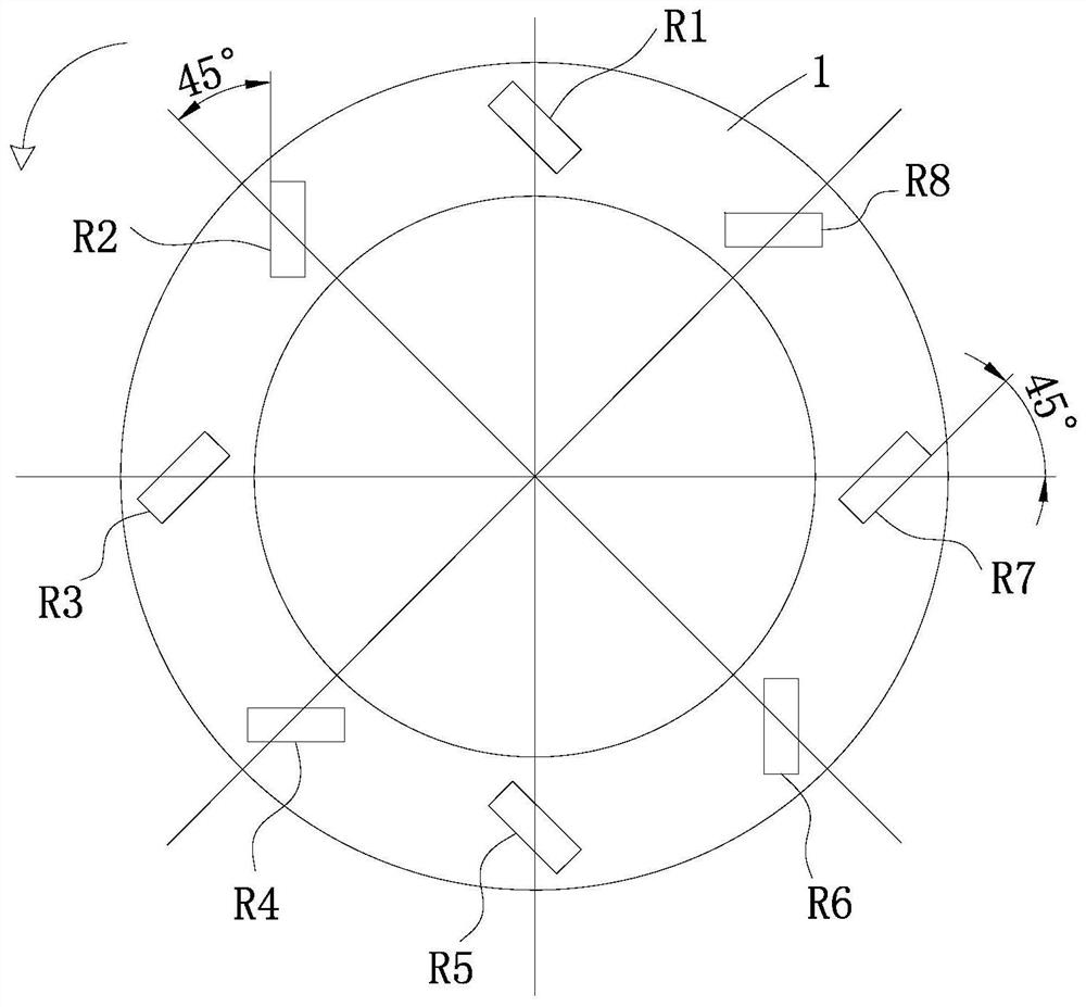
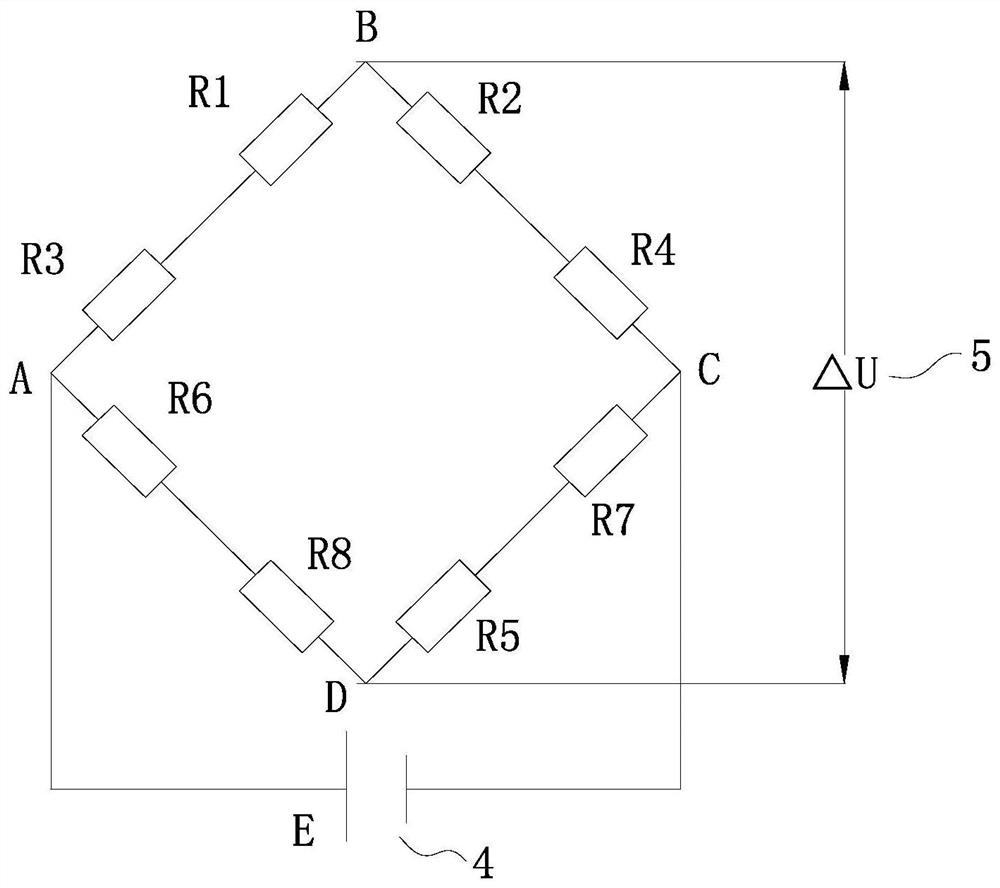
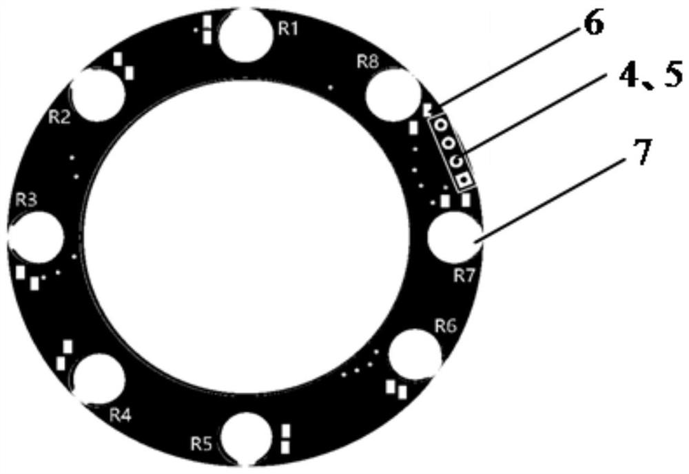
[0036] exist figure 1 Contains the harmonic reducer flexible spline 1 and the strain gauge; in figure 2 Contains power input terminal 4 and voltage output terminal 5; in image 3 Contains the rubber-based solder joints 6 of the strain gauges and the placement area 7 of the strain gauges. figure 2 The middle power supply input terminal 4 and the voltage output terminal 5 are in image 3 be reflected in.

[0037] Principle: By pasting eight strain gauges on the outer wall 1 of the harmonic reducer flexspline, the torque on the flexspline is directly sensed and measured with the strain gauges. Eight strain gauges with figure 1 The arrangement is pasted on the outer wall of the flexspline 1, and the acute angle between the length direction of the strain gauge and the radial line on the flexspline passing through the center of the strain gauge is 45 degrees, and the leads of the eight strain gauges are welded on the strain gauge On the rubber-based solder joint 6 of the elec...


PUM


Abstract

A method for measuring the output torque of a harmonic reducer flexspline, which relates to a measurement method, the steps of which are: eight strain gauges are evenly arranged on the surface of the harmonic reducer flexspline along its circumferential direction; each strain The length direction of the strain gauge is equal to the acute angle of the radial line angle on the flexspline passing through the center of the strain gauge, and the even-numbered and odd-numbered strain gauges are arranged alternately; the eight strain gauges are connected according to a full-bridge circuit, respectively : The first and third strain gauges are connected as the first side, the second and fourth strain gauges are connected as the second side, the fifth and seventh strain gauges are connected as the third side, and the sixth and eighth strain gauges are connected as the second side On the four sides, the eight strain gauges are connected according to a full bridge circuit; the output torque is calculated according to the voltage output. The invention has the characteristics of direct measurement, simple calculation and no extra flexibility to the harmonic reducer.

Description

technical field [0001] The invention relates to a measuring method, in particular to a measuring method for the flexible output torque of a harmonic reducer. It belongs to the technical field of torque detection. Background technique [0002] At present, for the control of the robot, the torque sensor is a necessary sensing device to realize the force feedback control of the robot. At present, most of the existing torque sensors for robots are installed at the end of the robot joints. This measurement method requires complex mathematical modeling of the robot. It is necessary to calculate the joint torque of the robot to accurately obtain the joint torque, so that the process of measuring torque Complicated, with a huge amount of computation. This method of installing torque sensors at the ends of robot joints is an indirect measurement of torque, which reduces the reliability of robot force feedback control. Contents of the invention [0003] The present invention prop...

Claims


Application Information

Patent Timeline
Patent Type & Authority Patents(China)
IPC IPC(8): G01L3/00G01L5/00
CPCG01L3/00G01L5/0061
Inventor 韩建达别东洋罗孟德
Owner NANKAI UNIV
Learn More