A follow-up control method, device, computer equipment and storage medium

A control method and technology of a computer program, applied in the field of photography, can solve the problems of not being sensitive enough to the action of the photographed object, difficult for the photographing equipment to accurately estimate the scale of the photographed object, unable to be in a back-to-back state for a long time, etc., and achieve the effect of good composition effect.

Active Publication Date: 2022-03-25
REMO TECH CO LTD
View PDF16 Cites 0 Cited by
  • Summary
  • Abstract
  • Description
  • Claims
  • Application Information

AI Technical Summary

Problems solved by technology

However, how to adjust the rotation angle of the gimbal according to the bounding box to follow up the target object is still a difficult problem
[0003] In the prior art, the face bounding box is directly placed at the center (or above the center) of the entire picture, but this control method has obvious disadvantages: first, it is not sensitive enough to the motion of the subject, when the subject When the limbs move, because the position of the face does not change, the shooting picture remains unchanged, so the movement of the limbs may exceed the shooting picture; the second is to restrict the movement of the subject, when the subject turns around, because the face cannot be observed First, the shooting equipment can only keep the original shooting angle unchanged, so the equipment requires that the subject cannot be in the state of facing away for a long time, and if it is in the state of facing away, it cannot move in a large range; the third is that there is a certain difficulty in estimating the size of the subject , when the subject is sideways, the bounding box of the face is deformed, and it is difficult for the shooting equipment to accurately estimate the scale of the real subject at this time, so it is difficult to set a reasonable focal length value

Method used


Image

  • A follow-up control method, device, computer equipment and storage medium
  • A follow-up control method, device, computer equipment and storage medium
  • A follow-up control method, device, computer equipment and storage medium

Examples


Embodiment 1

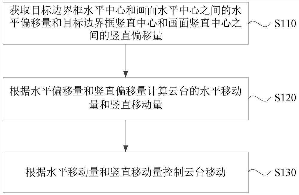
[0045] figure 1 This is a flowchart of a tracking control method provided in Embodiment 1 of the present invention. This embodiment can be applied to the situation of tracking control. The method can be executed by the tracking control device in this embodiment of the present invention. The device can use implemented in software and / or hardware, such as figure 1 As shown, the method specifically includes the following steps:

[0046] S110: Obtain the horizontal offset between the horizontal center of the target bounding box and the horizontal center of the picture and the vertical offset between the vertical center of the target bounding box and the vertical center of the picture.

[0047]The target bounding box is a portrait bounding box, and the target bounding box may be a portrait bounding box including only one human object, or may be a portrait bounding box including two or more human objects. limit. That is, a follow-up shot can be performed for one person object, or...

Embodiment 2

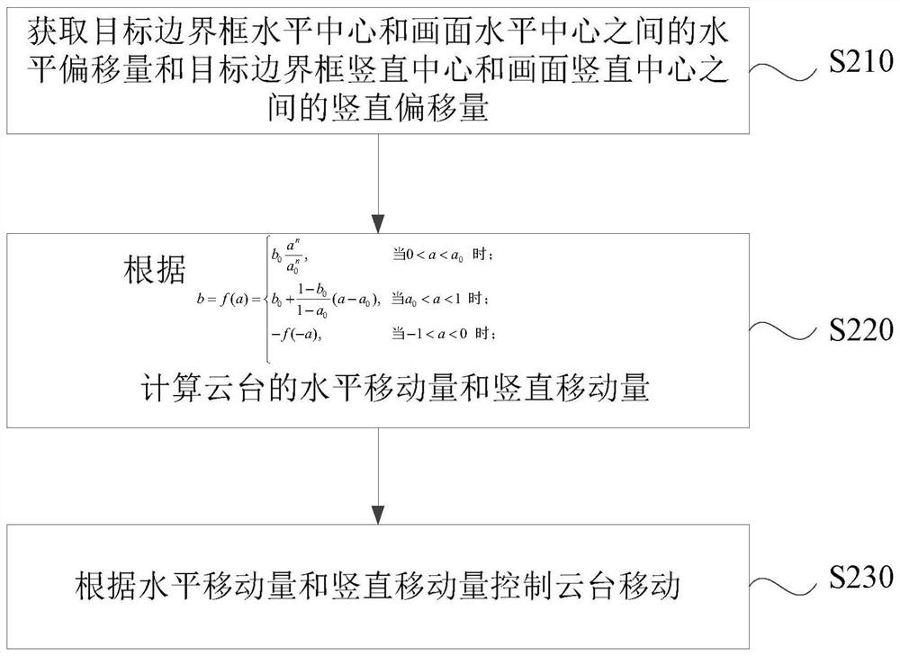
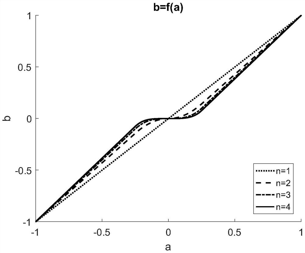
[0060] figure 2 This is a flowchart of a tracking control method in Embodiment 2 of the present invention. This embodiment is optimized on the basis of the above-mentioned embodiment. As an implementation form of this embodiment of the present invention, in this embodiment, the formula is Calculate the horizontal and vertical movement of the PTZ. Combine below figure 2 , the above situation of the tracking control method according to the embodiment of the present invention will be described.

[0061] like figure 2 As shown, the method of this embodiment specifically includes the following steps:

[0062] S210: Obtain the horizontal offset between the horizontal center of the target bounding box and the horizontal center of the picture and the vertical offset between the vertical center of the target bounding box and the vertical center of the picture.

[0063] Specifically, the coordinates of the upper left corner of the shooting screen are marked as (0,0), the coordin...

Embodiment 3

[0095] Figure 5 This is a schematic structural diagram of a tracking control device provided in Embodiment 3 of the present invention. This embodiment can be applied to the situation of tracking control, the device can be implemented in software and / or hardware, and the device can be integrated in any device that provides tracking control, such as Figure 5 As shown, the tracking control device specifically includes: an acquisition module 310 , a calculation module 320 and a control module 330 .

[0096] Wherein, the obtaining module 310 is used to obtain the horizontal offset between the horizontal center of the target bounding box and the horizontal center of the picture and the vertical offset between the vertical center of the target bounding box and the vertical center of the picture;

[0097] a calculation module 320, configured to calculate the horizontal movement amount and the vertical movement amount of the PTZ according to the horizontal offset and the vertical of...


PUM


Abstract

The invention discloses a follow-up control method, device, computer equipment and storage medium. The method includes: obtaining a horizontal offset between the horizontal center of the target bounding box and the horizontal center of the screen and a vertical offset between the vertical center of the target bounding box and the vertical center of the screen; according to the horizontal offset and The vertical offset calculates the horizontal movement amount and the vertical movement amount of the pan-tilt; the movement of the pan-tilt is controlled according to the horizontal movement amount and the vertical movement amount. The invention controls the movement of the pan-tilt according to the bounding box of the target, so as to realize the automatic follow-up shooting of the target and achieve a good composition effect.

Description

technical field [0001] The present invention relates to the field of camera technology, and in particular, to a tracking control method, device, computer equipment and storage medium. Background technique [0002] With the widespread application of deep learning technology, it has become a no-brainer to obtain portrait bounding boxes or face bounding boxes from captured images. However, how to adjust the rotation angle of the gimbal to follow the target object according to the bounding box is still a difficult problem. [0003] In the prior art, the face bounding box is directly placed at the center (or the upper center) of the entire picture, but this control method has obvious disadvantages: first, it is not sensitive enough to the action of the shooting object, and when the shooting object is not sensitive enough, When the limbs move, because the position of the face does not change and the shooting picture does not change, the movements of the limbs may exceed the shoot...

Claims


Application Information

Patent Timeline
Patent Type & Authority Patents(China)
IPC IPC(8): G05D3/12
CPCG05D3/12
Inventor 王禹张明
Owner REMO TECH CO LTD
Why Eureka
Try Eureka