Contact monitoring device of high-voltage direct-current relay

A high-voltage direct current, monitoring device technology, applied in the direction of relays, electromagnetic relays, detailed information of electromagnetic relays, etc., can solve problems such as unstable electrical equipment, poor contact of conductive parts, and unsmooth sliding, so as to improve safety and stability , Avoid sliding is not smooth, reduce the effect of maintenance and troubleshooting time

Inactive Publication Date: 2019-09-10
中汇瑞德电子(芜湖)有限公司
View PDF5 Cites 4 Cited by
  • Summary
  • Abstract
  • Description
  • Claims
  • Application Information

AI Technical Summary

Problems solved by technology

[0002] The electromagnetic relay is an automatic switch that uses a smaller current and a lower voltage to control a larger current and a higher voltage. The function of the existing switch is to use an internal electromagnet to The coil of the electromagnet is fed with a small current, so that the electromagnet generates a magnetic field, and the armature is attracted or released by the generation or disappearance of the magnetic field, thereby driving the conductive shrapnel to attract or disconnect, so as to realize the conduction of the large current loop However, after the relay has been used for a long time, due to the aging of the internal parts of the relay, the stability is getting worse and worse, such as the iron core of the relay does not slide smoothly, and the conductive parts are in poor contact. The function is unstable or invalid, which requires a lot of manpower for maintenance

Method used


Image

  • Contact monitoring device of high-voltage direct-current relay
  • Contact monitoring device of high-voltage direct-current relay
  • Contact monitoring device of high-voltage direct-current relay

Examples


Embodiment Construction

[0025] The following will clearly and completely describe the technical solutions in the embodiments of the present invention with reference to the accompanying drawings in the embodiments of the present invention. Obviously, the described embodiments are only some, not all, embodiments of the present invention. Based on the embodiments of the present invention, all other embodiments obtained by persons of ordinary skill in the art without making creative efforts belong to the protection scope of the present invention.

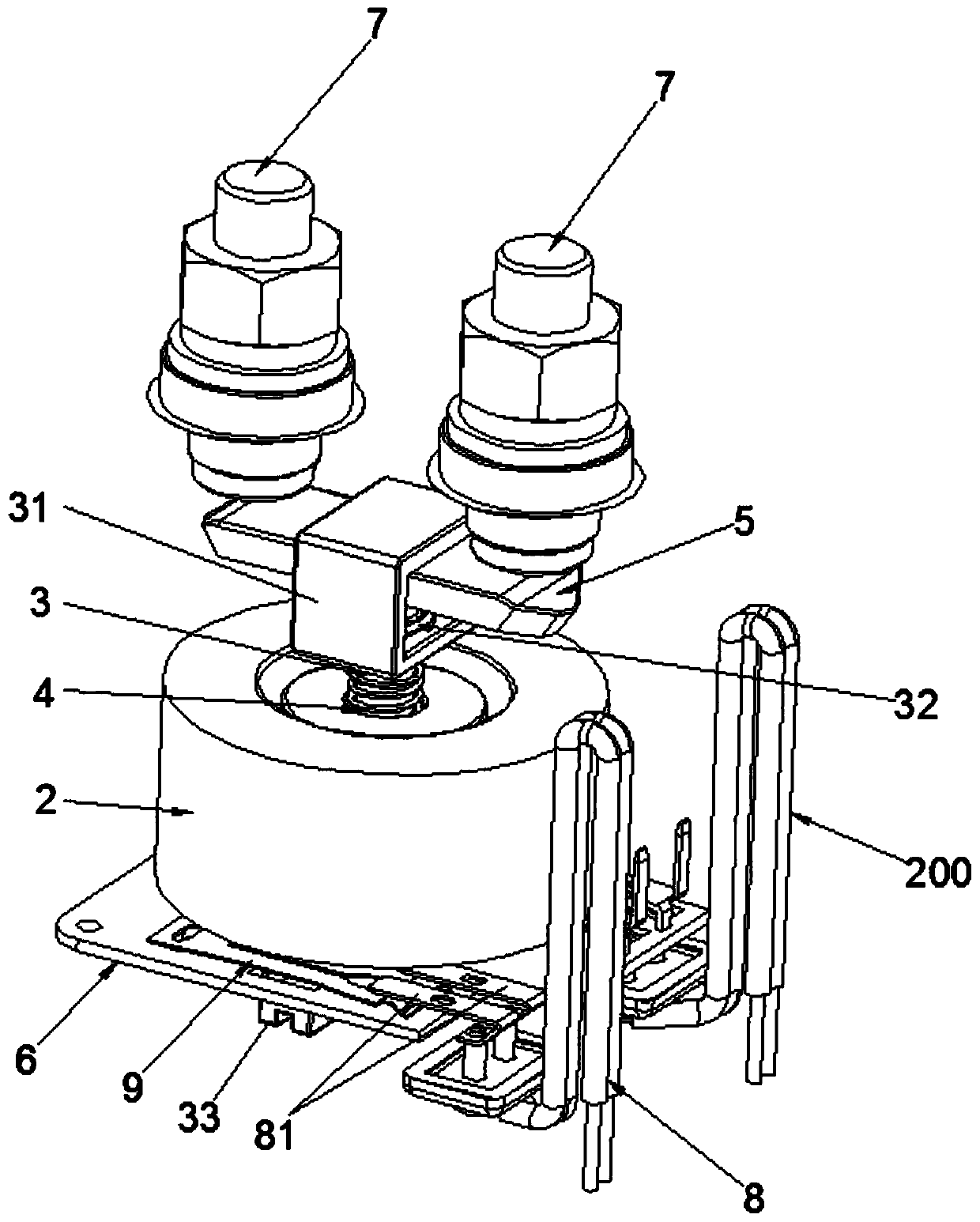
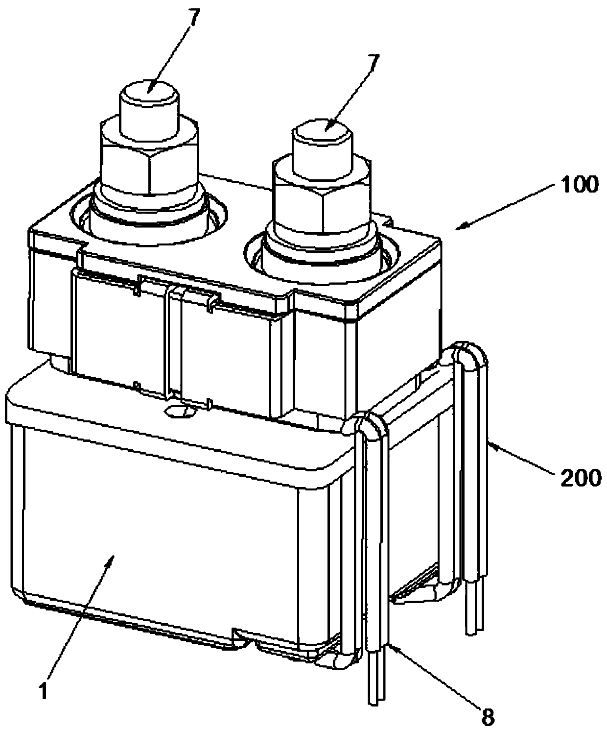
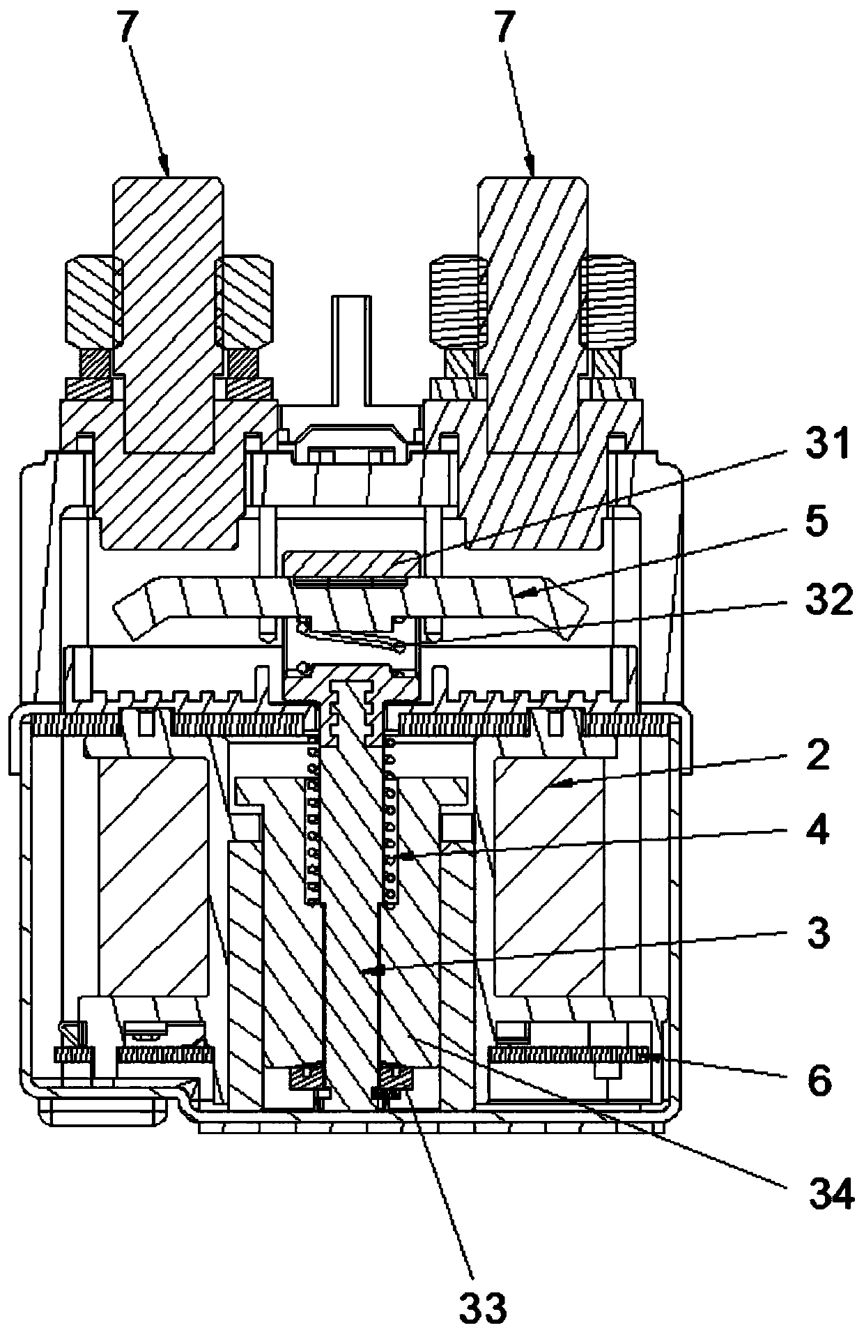
[0026] see Figure 1-6 , an embodiment provided by the present invention: a contact monitoring device for a high voltage direct current relay, comprising a high voltage direct current relay 100, a working circuit 200 and a contact detection mechanism, the contact detection mechanism is placed below the high voltage direct current relay 100, and One end of the bottom of the high voltage direct current relay 100 is connected with a working circuit 200;

[0027]...


PUM


Abstract

The invention discloses a contact monitoring device of a high-voltage direct-current relay. The contact monitoring device comprises the high-voltage direct-current relay, a working circuit and a contact detection mechanism; the contact detection mechanism is arranged below the high-voltage direct-current relay; one end of the bottom of the high-voltage direct-current relay is connected with the working circuit; the high-voltage direct-current relay comprises a shell, a coil, an iron core, an elastic element, a movable contact platform, a circuit board and two load terminals; and the contact detection mechanism comprises a signal circuit and a conductive spring piece. A push rod is driven by lifting the iron core to push the conductive spring piece to rise, so that the iron core drives theconductive spring piece to be in contact with a connecting terminal while moving, and then the signal circuit is turned on; and a working state of the device is monitored through an indicating lamp state of the signal circuit, and whether the two load terminals are truly closed or not is known in real time, so that the time for overhauling and fault checking after power failure of the high-voltagedirect-current relay is shortened, and the labor maintenance cost is effectively reduced.

Description

technical field [0001] The invention relates to a relay, in particular to a contact monitoring device for a high voltage direct current relay. Background technique [0002] The electromagnetic relay is an automatic switch that uses a smaller current and a lower voltage to control a larger current and a higher voltage. The function of the existing switch is to use an internal electromagnet to The coil of the electromagnet is fed with a small current, so that the electromagnet generates a magnetic field, and the armature is attracted or released by the generation or disappearance of the magnetic field, thereby driving the conductive shrapnel to attract or disconnect, so as to realize the conduction of the large current loop However, after the relay has been used for a long time, due to the aging of the internal parts of the relay, the stability is getting worse and worse, such as the iron core of the relay does not slide smoothly, and the conductive parts are in poor contact. ...

Claims


Application Information

Patent Timeline
Patent Type & Authority Applications(China)
IPC IPC(8): H01H51/00H01H50/08H01H50/18
CPCH01H50/08H01H50/18H01H51/00
Inventor 杜展
Owner 中汇瑞德电子(芜湖)有限公司
Why Eureka
Try Eureka