

Detection device for sleeper bolts
A detection device and bolt technology, which is applied to measurement devices, optical devices, instruments, etc., can solve the problems of inability to collect bolt profiles, cumbersome calibration process, easy to block laser lines, etc., to ensure the real-time performance and robustness of the system. , the effect of improving the detection speed
- Summary
- Abstract
- Description
- Claims
- Application Information
AI Technical Summary
Problems solved by technology
Method used
Image

Examples
Embodiment 1
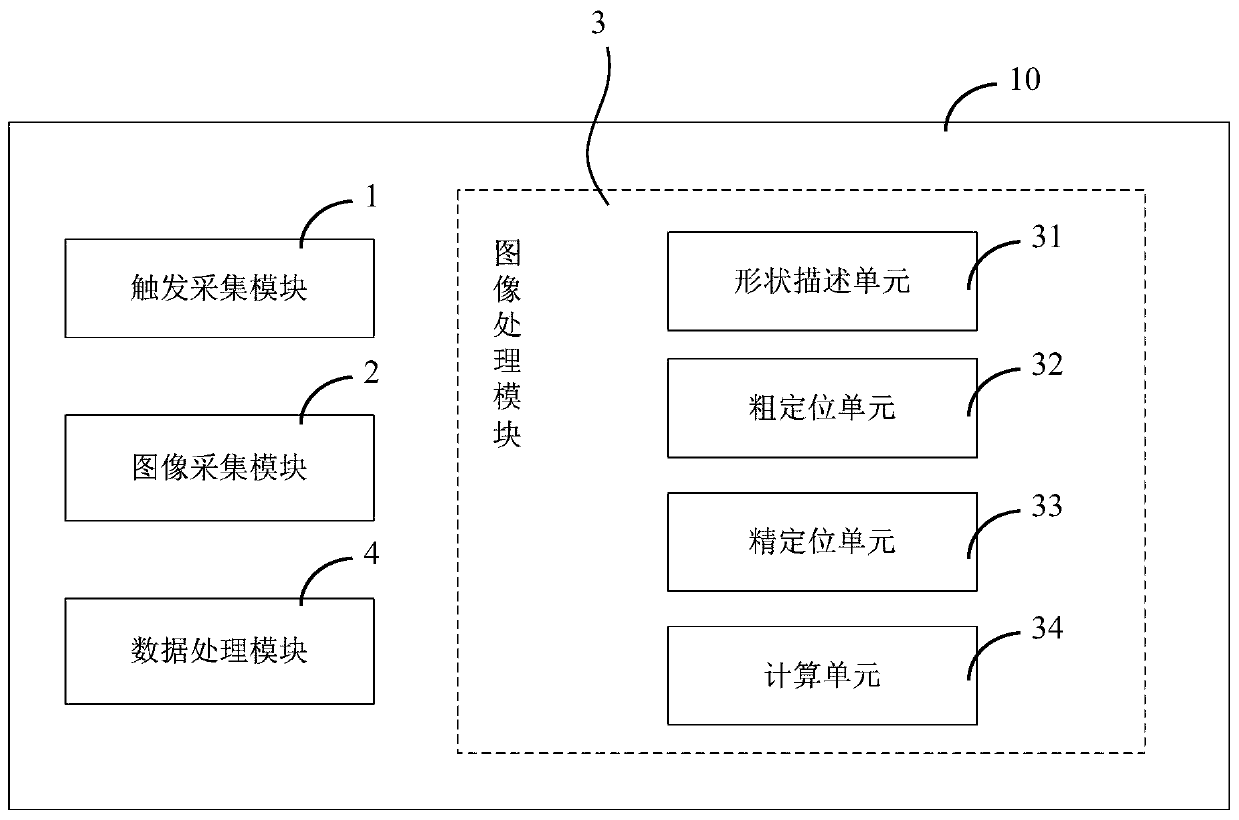
[0062] as attached figure 1 As shown, an embodiment of the sleeper bolt detection device of the present invention specifically includes:
[0063] The collection module 1 is triggered to obtain the position to be collected of the sleeper bolt image. The trigger acquisition module 1 is mainly composed of a position sensor, a logic circuit, etc., and can obtain position information with different precisions through configuration, and transmit reference information such as multiple trigger signals and trigger indexes at the same time.
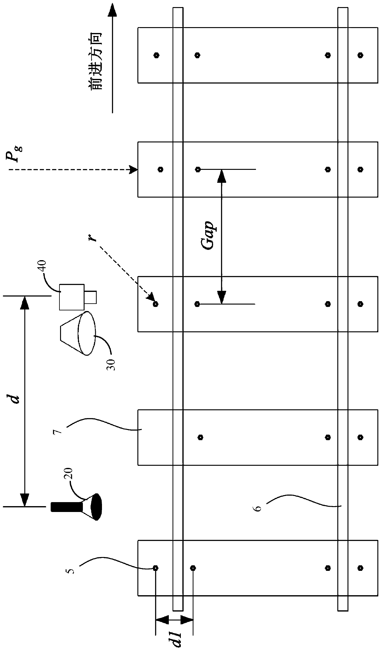
[0064] The image acquisition module 2 acquires the plane image data of the sleeper bolts 5 according to the position to be acquired. The image acquisition module 2 further includes a light source 30 and a camera 40 , and the image acquisition module 2 acquires planar image data of the sleeper bolts 5 according to the trigger pulse sent by the trigger acquisition module 1 . When the current position of the image acquisition module 2 is greater tha...
Embodiment 2
[0088] as attached Figure 5 And attached Figure 6 As shown, an embodiment of a sleeper bolt detection method based on the device described in Embodiment 1, specifically comprises the following steps:
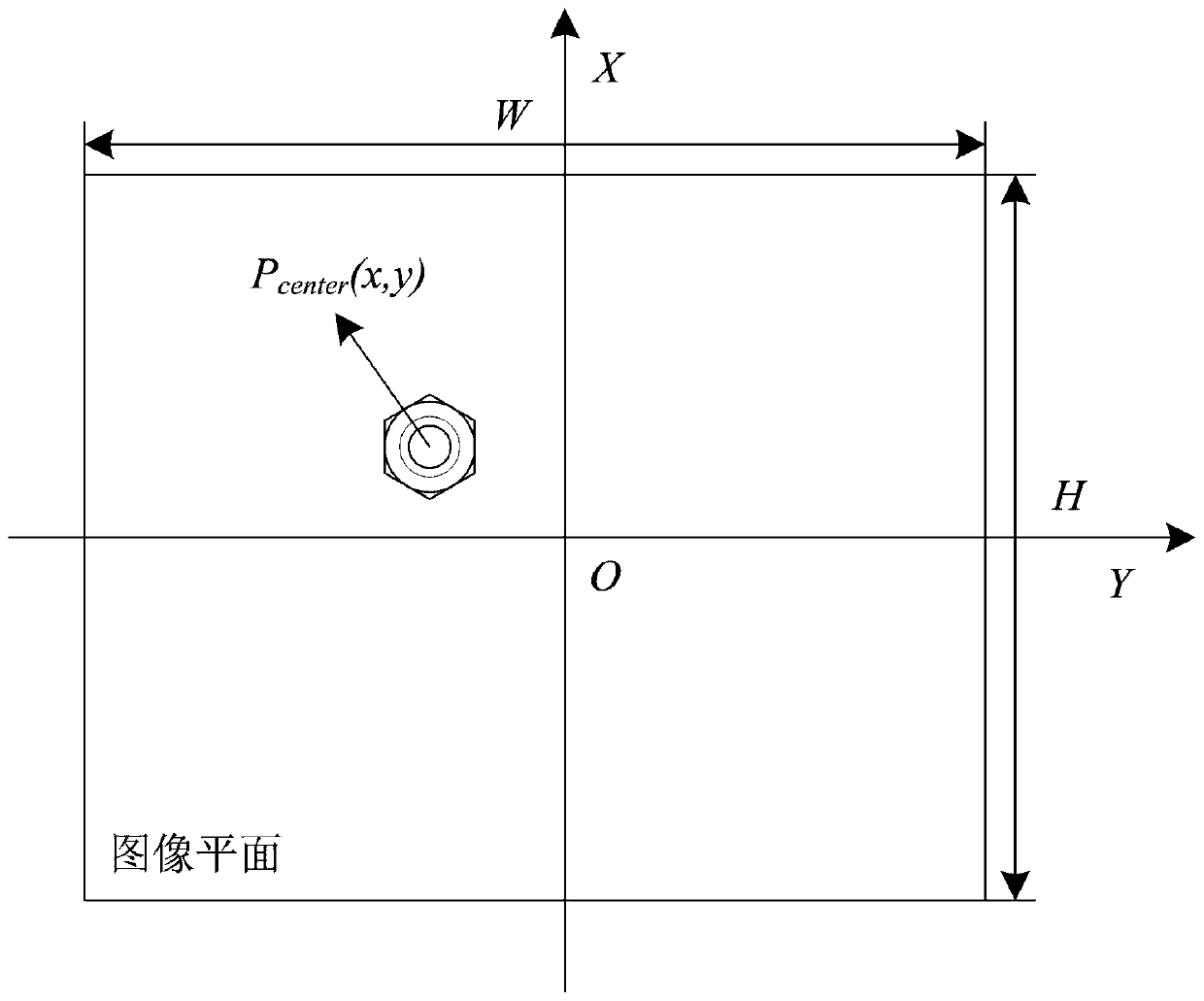
[0089] A) Obtain the position to be collected of the sleeper bolt image; first, the device is initialized, and the position to be collected of the first frame of the sleeper bolt image is the assignment when the sleeper bolt detection device 10 performs system initialization, when the current position of the image acquisition reaches the first frame of sleeper Collect a frame of image when the position of the bolt image is to be collected, and record the width W, height H of the collected image plane, and the current shooting position S 0 ;
[0090] As a preferred embodiment of the present invention, if the sleeper bolts are detected in the first frame of sleeper bolt images collected, it is judged that the sleeper bolt image acquisition position is the position of the sleep...
PUM
 Abstract
Description
Claims
Application Information