A sleeper bolt detection device

A technology for detecting devices and bolts, which is applied to measuring devices, optical devices, instruments, etc., can solve the problems of inability to collect bolt profiles, easy occlusion of laser lines, and cumbersome calibration process, so as to ensure the real-time performance and robustness of the system. , the effect of improving the detection speed

Active Publication Date: 2021-03-02
ZHUZHOU TIMES ELECTRONICS TECH CO LTD
View PDF14 Cites 0 Cited by
  • Summary
  • Abstract
  • Description
  • Claims
  • Application Information

AI Technical Summary

Problems solved by technology

[0007] In view of this, the object of the present invention is to provide a sleeper bolt detection device to solve the problem that the existing sleeper bolt detection device not only has a complex structure, high cost, and cumbersome calibration process, but also has a height exceeding the bolt due to the large angle between the camera and the laser. The background objects can easily block the laser line, so the bolt profile cannot be collected, resulting in missed detection. At the same time, there is a technical problem of mileage accumulation error in the positioning of the forward direction by using the line scan image collection method.

Method used


Image

  • A sleeper bolt detection device
  • A sleeper bolt detection device
  • A sleeper bolt detection device

Examples


Embodiment 1

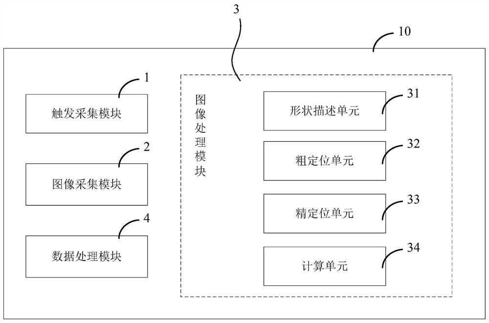
[0062]As attachedfigure 1 As shown, an embodiment of the sleeper bolt detection device of the present invention specifically includes:

[0063]Trigger the acquisition module 1 to acquire the position to be acquired of the sleeper bolt image. The trigger acquisition module 1 is mainly composed of a position sensor, a logic circuit, etc., through configuration, position information of different precisions can be obtained, and reference information such as multiple trigger signals and trigger indexes can be transmitted at the same time.

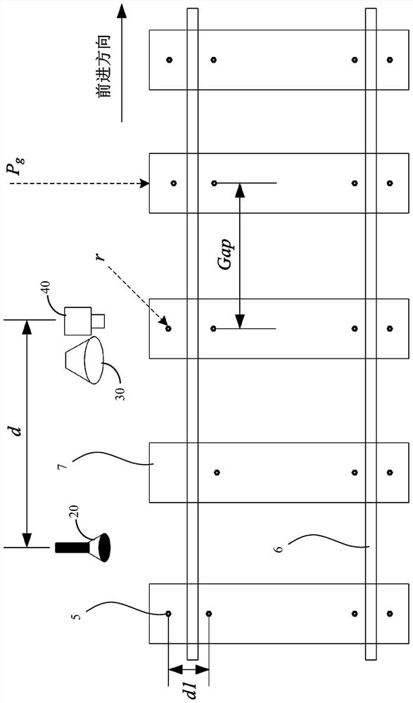
[0064]The image acquisition module 2 acquires the plane image data of the sleeper bolt 5 according to the position to be acquired. The image acquisition module 2 further includes a light source 30 and a camera 40. The image acquisition module 2 acquires plane image data of the sleeper bolt 5 according to the trigger pulse sent by the trigger acquisition module 1. When the current position of the image acquisition module 2 is greater than or equal to the pos...

Embodiment 2

[0088]As attachedFigure 5 AndFigure 6 As shown, an embodiment of a sleeper bolt detection method based on the device described in embodiment 1, specifically includes the following steps:

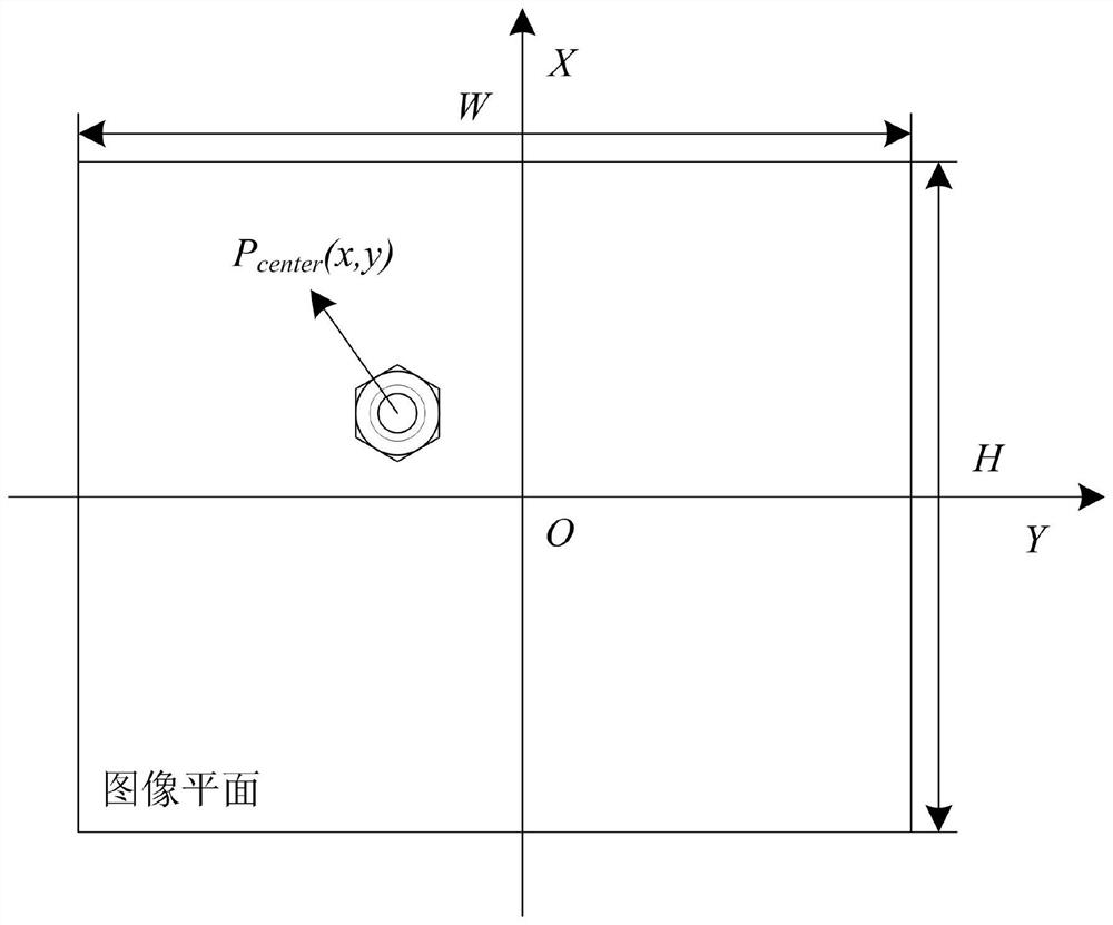
[0089]A) Acquire the position of the sleeper bolt image to be collected; first, the device is initialized. The position to be collected of the sleeper bolt image of the first frame is the value assigned when the sleeper bolt detection device 10 performs the system initialization. When the current position of the image collection reaches the sleeper of the first frame Collect a frame of image when the bolt image is to be collected, and record the width W, height H of the collected image plane, and the current shooting position S0;

[0090]As a preferred embodiment of the present invention, if a sleeper bolt is detected in the first frame of the collected sleeper bolt image, it is determined that the sleeper bolt image collection position is the position of the sleeper bolt; if the first frame of the coll...


PUM


Abstract

The invention discloses a sleeper bolt detection device, comprising: a trigger acquisition module, which acquires the position to be collected of the image of the sleeper bolt; an image acquisition module, which acquires the plane image data of the sleeper bolt according to the position to be collected; Obtain the shape description from the plane image data, identify the bolt area according to the shape description, perform circle fitting on the bolt area, and extract the coordinates of the center of the circle; the data processing module calculates the center offset of the sleeper bolt and the image of the next frame of the sleeper bolt according to the coordinates of the center of the circle The location to be collected. The present invention can solve the problem that the existing sleeper bolt detection device is not only complex in structure, high in cost, and cumbersome in the calibration process, but also because there is a large angle between the camera and the laser, background objects whose height exceeds the bolt can easily block the laser line, so the bolt profile cannot be collected , which in turn leads to missed detection, and at the same time, there is a technical problem of a certain mileage accumulation error in the positioning of the forward direction by using the line scan image acquisition method.

Description

Technical field[0001]The invention relates to the technical field of visual image detection, in particular to a sleeper bolt position detection device applied to the field of rail transit.Background technique[0002]The detection of the position of sleeper bolts is an important part of railway line maintenance. It is mainly used to obtain the offset Y of the sleeper bolt relative to the operating device along the track forward direction, the offset X in the vertical track direction, and the height offset. Z. The position information of the sleeper bolts can be used to guide the rail-changing operation of the rail-changing car, the oiling operation of the sleeper bolt oiling trolley, the automatic tightening operation of the sleeper bolts, and the automatic tamping operation.[0003]At present, the detection methods of sleeper bolts mainly include manual visual inspection, contact switch or metal sensor detection, and 3D point cloud detection. Among them, the manual visual inspection met...

Claims


Application Information

Patent Timeline
Patent Type & Authority Patents(China)
IPC IPC(8): G01B11/00
CPCG01B11/00
Inventor 邱新华王文昆刘兴平关伟薛双纲曹辉季育文张磊聂肃
Owner ZHUZHOU TIMES ELECTRONICS TECH CO LTD
Why Eureka
Try Eureka