
Antenna phase center test system with north pointing function

A technology of antenna phase center and test system, which is applied in the directions of measuring devices, surveying and navigation, and navigation through speed/acceleration measurement, etc., which can solve the problem of heavy test workload, difficulty in achieving accurate north pointing, and inability to accurately achieve angles by manual methods Rotation and other issues

Active Publication Date: 2019-09-13
NANJING INST OF MEASUREMENT & TESTING TECH
View PDF7 Cites 2 Cited by
  • Summary
  • Abstract
  • Description
  • Claims
  • Application Information

AI Technical Summary

Problems solved by technology

Obviously, there are many problems such as heavy test workload, long test time, low test efficiency, and insufficient test accuracy when adopting this fully manual test method.
When using the traditional manual method for testing, due to the lack of a strict north pointing method, the north can only be roughly judged manually, it is difficult to achieve accurate north pointing, and the direction can only be roughly estimated; secondly, rotate to 90 degrees, 180 degrees, and 270 degrees in sequence according to the regulations , the manual method can’t realize the rotation of the angle accurately, it depends entirely on the subjective feeling and experience of the tester
In the traditional manual measurement, the test of each antenna or terminal needs to be turned on and off four times, and the angle is adjusted four times. Seven terminals need to be operated 56 times in total, which is time-consuming and laborious.

Method used

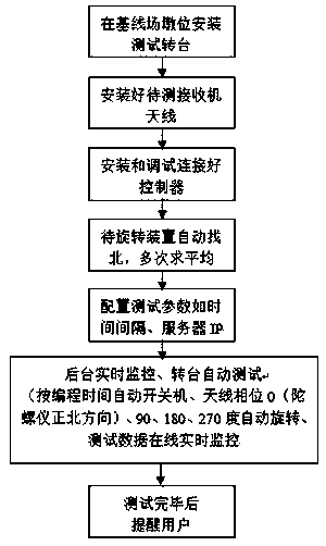

Image

  • Antenna phase center test system with north pointing function
  • Antenna phase center test system with north pointing function
  • Antenna phase center test system with north pointing function

Examples


Embodiment Construction

[0025] The present invention will be further described below in conjunction with the accompanying drawings. The following examples are only used to illustrate the technical solution of the present invention more clearly, but not to limit the protection scope of the present invention.

[0026] In the description of the present invention, the orientations or positional relationships indicated by the terms "upper", "lower", etc. are based on the orientations or positional relationships shown in the drawings. composition and operation, therefore, should not be construed as limiting the invention.

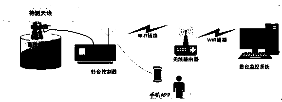
[0027] The antenna phase center testing system with the function of pointing north provided by the present invention includes such as figure 1 The shown turntable and control module also include a user receiver and a data processing module.

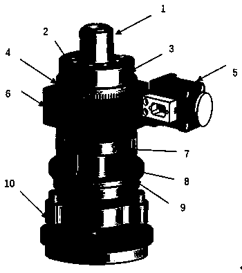
[0028] Turntable: such as image 3 As shown, the turntable includes a base 10 with a forced centering function, the base 10 is connected with a...


PUM


Abstract

The invention discloses an antenna phase center test system with a north pointing function. The antenna phase center test system comprises a rotary table, a control module, a user receiver and a dataprocessing module; the rotary table comprises a motor, a transmission platform which is internally provided with a worm and gear set, a gyroscope mounting cavity in which a gyroscope module is arranged, and a fixture for mounting an antenna; the stepping motor receives an instruction sent by the control module, the antenna mounted on the fixture is controlled by the worm and gear set to rotate toa set angle, the user receiver acquires a satellite navigation signal sent when the antenna rotates to the set angle, and the data processing module calculates an antenna phase center according to thesatellite navigation signal acquired by the user receiver; and according to the scheme, accurate north search of the antenna is implemented, an unmanned test mode of the antenna phase center of a baseline field is implemented, promotion and transformation from manual test to automatic test are completed, test working efficiency is improved, test cost is reduced, and management of the field test work is simpler and more efficient.

Description

technical field [0001] The invention relates to an antenna phase center test system with the function of pointing north, and belongs to the technical field of antenna phase center test. Background technique [0002] Antenna phase center (average antenna phase center) refers to the electrical center of a microwave antenna. Its theoretical design should be consistent with the geometric center of the antenna. The difference between the antenna phase center and the geometric center is called the antenna phase center deviation. The test of the antenna phase center requires that the north marks on all the antennas under test point to the true north at the same time during the test. The measured antennas in the first measurement section are all pointing north, observe for a period of time (1.5h); then fix the antenna G1 not moving, rotate the other antenna G2 clockwise, rotate 90°, 180°, 270° in turn, and measure 3 periods , to obtain the baseline vectors of each time period res...

Claims


Application Information

Patent Timeline
Patent Type & Authority Applications(China)
IPC IPC(8): G01C21/18G01C17/00
CPCG01C21/18G01C17/00
Inventor 曹相张杰陈倩倩张欢魏建雄
Owner NANJING INST OF MEASUREMENT & TESTING TECH
Learn More