Stable-to-mount transformer box with heat dissipation function

A transformer and function technology, applied in the field of transformer boxes, can solve the problems of small footprint of the transformer box, inconvenient inspection of the transformer box, inconvenient installation of the transformer, etc., and achieves good protection, novel structure and low cost. Effect

Inactive Publication Date: 2019-09-13
许昌中天宇光电气技术有限公司
View PDF5 Cites 4 Cited by
  • Summary
  • Abstract
  • Description
  • Claims
  • Application Information

AI Technical Summary

Problems solved by technology

[0002] In the prior art, the transformer is installed in the transformer box to ensure the stability of the transformer during operation. Although the transformer box has the functions of sheltering from wind, rain, and dust, but at the same time, due to the relatively sealed structure of the box, the transformer A large amount of heat generated during work cannot be discharged in time. The shape of the transformer box is regular and occupies a small space, but it is unstable when placed. The transformer vibrates during work. If the center of gravity of the transformer box is unstable, accidents may occur during work. , In addition, it is inconvenient to install the transformer inside the transformer box, and the transformer coil cannot be well installed in the transformer box. If the transformer coil is not installed stably in the transformer box, the transformer coils may be short-circuited due to mutual contact or even extrusion. It is not convenient to check the condition of the transformer box when the transformer is installed in the transformer box for maintenance, which is not conducive to popularization and use, and the cost is high; therefore, a transformer box with stable installation and heat dissipation function is needed

Method used


Image

  • Stable-to-mount transformer box with heat dissipation function
  • Stable-to-mount transformer box with heat dissipation function

Examples


Embodiment 1

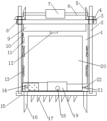
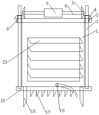
[0016] Such as Figure 1-2 As shown, a transformer box with stable installation and heat dissipation function includes a housing 1, a fixing plate 8 is arranged on the top of the housing 1, and pointed ground nails 16 are provided at the four corners of the bottom of the housing 1 , the bottom of the shell 1 is provided with a counterweight base 15, and the bottom of the counterweight base 15 is provided with pointed fixing nails 17, and the left and right sides of the counterweight base 15 are fixedly provided with screw rods 2, so The screw rod 2 runs through the fixed plate 8 and is provided with a first gear 4 above, and the inner side of the first gear 4 is meshed with a second gear 5, and the second gear 5 is fixedly connected with a rotating shaft 6, so The rotating shaft 6 is commonly connected with a dual-output shaft motor 7, a dry powder bin 9 is provided on the top of the housing 1, a solenoid valve 12 is arranged below the dry powder bin 9, and a side wall inside ...

Embodiment 2

[0019] Such as Figure 1-2 As shown, a transformer box with stable installation and heat dissipation function includes a housing 1, a fixing plate 8 is arranged on the top of the housing 1, and pointed ground nails 16 are provided at the four corners of the bottom of the housing 1 , the bottom of the shell 1 is provided with a counterweight base 15, and the bottom of the counterweight base 15 is provided with pointed fixing nails 17, and the left and right sides of the counterweight base 15 are fixedly provided with screw rods 2, so The screw rod 2 runs through the fixed plate 8 and is provided with a first gear 4 above, and the inner side of the first gear 4 is meshed with a second gear 5, and the second gear 5 is fixedly connected with a rotating shaft 6, so The rotating shaft 6 is commonly connected with a dual-output shaft motor 7, a dry powder bin 9 is provided on the top of the housing 1, a solenoid valve 12 is arranged below the dry powder bin 9, and a side wall inside ...


PUM


Abstract

The invention relates to a stable-to-mount transformer box with a heat dissipation function. The transformer box comprises a shell; a fixed plate is arranged above the shell; pointed type ground grabbing nails are arranged at the four corners of the bottom of the shell; a counterweight base is arranged below the shell; screw rods are fixedly arranged on the left side and the right side of the counterweight base; the screw rods run through the fixed plate and are provided with first gears; the inner sides of the first gears are meshed with second gears; the second gears are fixedly connected with rotating shafts; the rotating shafts are connected with a double-output shaft motor; a dry powder bin is arranged at the top in the shell; an electromagnetic valve is arranged below the dry powderbin; a power switch, a temperature and humidity sensor and an exhaust fan are arranged on the side walls in the shell; the exhaust fan is connected with a heat exchanger through a pipeline; a transformer shell is arranged in the shell; hydraulic devices are arranged on the left side and the right side of the shell; and hydraulic rods are connected to the inner sides of the hydraulic devices. The transformer box has the advantages of being good in protection performance, timely in heat dissipation, firm in fixation and capable of preventing a fire.

Description

technical field [0001] The invention relates to the technical field of transformer boxes, in particular to a transformer box with stable installation and heat dissipation function. Background technique [0002] In the prior art, the transformer is installed in the transformer box to ensure the stability of the transformer during operation. Although the transformer box has the functions of sheltering from wind, rain, and dust, but at the same time, due to the relatively sealed structure of the box, the transformer A large amount of heat generated during work cannot be discharged in time. The shape of the transformer box is regular and occupies a small space, but it is unstable when placed. The transformer vibrates during work. If the center of gravity of the transformer box is unstable, accidents may occur during work. , In addition, it is inconvenient to install the transformer inside the transformer box, and the transformer coil cannot be well installed in the transformer b...

Claims


Application Information

Patent Timeline
Patent Type & Authority Applications(China)
IPC IPC(8): H01F27/06H01F27/08H01F27/02H01F27/40A62C3/16
CPCA62C3/16H01F27/02H01F27/025H01F27/06H01F27/085H01F27/40H01F27/402H01F2027/406
Inventor 李蕾玉王留杰黄永恒石玉林
Owner 许昌中天宇光电气技术有限公司
Why Eureka
Try Eureka