Welding method of yg8 cemented carbide workpiece and dc53 cold work die steel workpiece

A cold work die steel, cemented carbide technology, applied in welding equipment, manufacturing tools, metal processing equipment, etc., can solve problems such as low welding rate, and achieve the effect of good strength and no cracks

Active Publication Date: 2021-06-08
JIAXING NANYANG POLYTECHNIC INST +1
View PDF7 Cites 0 Cited by
  • Summary
  • Abstract
  • Description
  • Claims
  • Application Information

AI Technical Summary

Problems solved by technology

[0003] The invention provides a welding method of YG8 hard alloy workpiece and DC53 cold work die steel workpiece with high welding rate, which solves the problem of low welding rate when welding YG8 hard alloy workpiece and DC53 cold work die steel workpiece in the existing method The problem

Method used


Image

  • Welding method of yg8 cemented carbide workpiece and dc53 cold work die steel workpiece
  • Welding method of yg8 cemented carbide workpiece and dc53 cold work die steel workpiece
  • Welding method of yg8 cemented carbide workpiece and dc53 cold work die steel workpiece

Examples


Embodiment 1

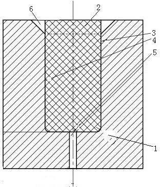
[0028] Embodiment one, see figure 1 , a YG8 hard alloy workpiece and DC53 cold work die steel workpiece welding method: the first step, remove the oil stain and oxide film at the welding place of the YG8 hard alloy workpiece 1 to be welded, and remove the DC53 cold work die steel workpiece 2 to be welded The oil stain and oxide film at the welding place; in the second step, the welding place of the YG8 hard alloy workpiece to be welded and the welding place of the DC53 cold work die steel workpiece to be welded are butted together with a gap to form a weldment pair. The gap is filled with pure copper; specifically, a connecting hole 3 is opened in a YG8 hard alloy workpiece 1, and a connecting head 4 is formed on a DC53 cold work die steel workpiece. The connection holes are blind holes. An air extraction hole 5 is provided on the bottom wall of the connecting hole. The connector extends vertically. A bell mouth section 6 is arranged at the open end of the connecting hole. ...

Embodiment 2

[0030] Embodiment two, the difference with embodiment one is:

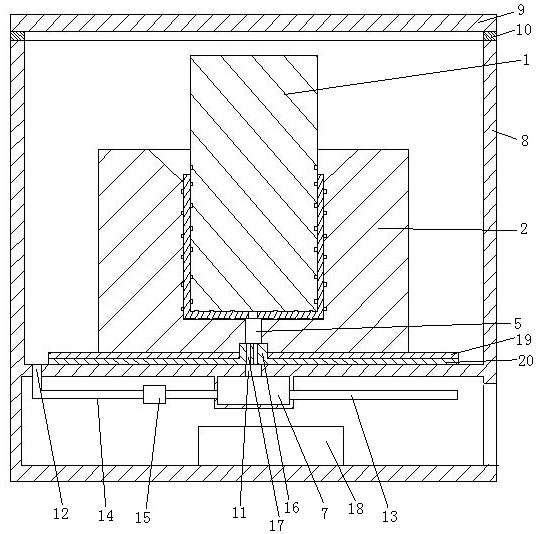
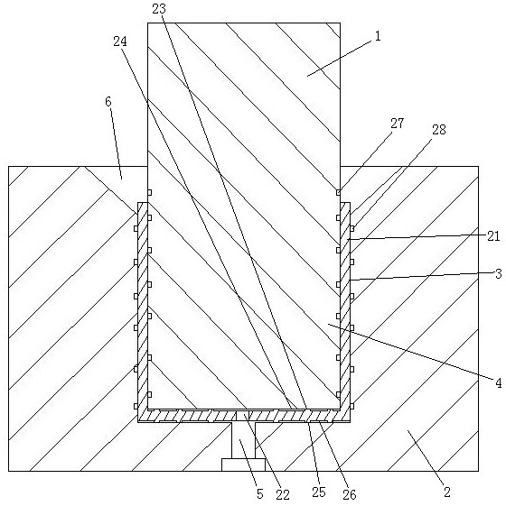
[0031] see figure 2 with image 3, the present embodiment is accomplished by a brazing device, which includes a vacuum chamber, a confluence chamber 7 and a heater for heating the vacuum chamber. The vacuum chamber includes a barrel body 8 and a barrel cover 9 . A sealing ring 10 is provided between the bung and the staving. The sealing ring is fixed on the upper end face of the staving, and the bung rests on the sealing ring. The barrel cover is sealed and connected with the barrel body by pressing the sealing ring to form a pressure difference between the outside and the inside of the vacuum chamber by evacuating the vacuum chamber. The vacuum chamber is provided with a first air outlet 11 and a second air outlet 12 . The confluence chamber cavity is provided with a vacuum port 13 and a pressure gauge (not shown in the figure). The first air outlet communicates with the confluence chamber. The second air...


PUM


Abstract

The invention relates to a welding method of YG8 hard alloy workpiece and DC53 cold work die steel workpiece: the first step is to remove the oil stain and oxide film at the welding place of the workpiece; the second step is to weld the welding place of the YG8 hard alloy workpiece to be welded at the same time The welding parts of the DC53 cold work die steel workpieces to be welded are butted together with a gap to form a weldment pair, and pure copper is filled in the gap; the third step is to heat the weldment pair to the set temperature in a vacuum environment and Keep the set time so that the pure copper melts and the YG8 hard alloy workpiece and the DC53 cold work die steel workpiece remain solid, and the molten pure copper penetrates into the YG8 hard alloy workpiece and the DC53 cold work die steel workpiece at the same time; the fourth step , Let the weldment pair cool down so that the YG8 cemented carbide workpiece and the DC53 cold work die steel workpiece are welded together. The invention has the advantage of high welding rate, and solves the problem of low welding rate when welding YG8 hard alloy workpieces and DC53 cold work die steel workpieces in the existing method.

Description

technical field [0001] The invention relates to the field of welding technology, in particular to a method for welding a YG8 hard alloy workpiece and a DC53 cold-working die steel workpiece. Background technique [0002] The method of welding YG8 cemented carbide workpieces and DC53 cold work die steel workpieces is usually brazing. When the existing brazing method is used to weld the YG8 hard alloy workpiece and the DC53 cold work die steel workpiece, there are defects of low welding rate and low connection strength at the weld. Contents of the invention [0003] The invention provides a welding method of YG8 hard alloy workpiece and DC53 cold work die steel workpiece with high welding rate, which solves the problem of low welding rate when welding YG8 hard alloy workpiece and DC53 cold work die steel workpiece in the existing method The problem. [0004] The above technical problems are solved through the following technical solutions: a welding method of YG8 hard allo...

Claims


Application Information

Patent Timeline
Patent Type & Authority Patents(China)
IPC IPC(8): B23K1/00B23K1/20B23K103/04
CPCB23K1/00B23K1/20B23K1/206B23K2103/04
Inventor 吴艳龚正朋王娟
Owner JIAXING NANYANG POLYTECHNIC INST
Why Eureka
Try Eureka