Internal-connection-type grout-stopping plug for grouting, and grouting method

A technology of grout stopper and connecting device, which is applied in the fields of soil protection, construction, and infrastructure engineering, etc. It can solve problems such as insufficient pressure, inability to automatically stop grout, poor apparent quality of the seal, etc., achieve quick disassembly and reduce cycle operations the effect of time

Inactive Publication Date: 2019-09-17
李博文
View PDF6 Cites 0 Cited by
  • Summary
  • Abstract
  • Description
  • Claims
  • Application Information

AI Technical Summary

Problems solved by technology

[0002] The grout stopper devices used in the field of pre-grouting engineering construction mostly use internal grout stoppers to stop the grout. The traditional grout stoppers have strict requirements on the grouting slurry due to the insufficient diameter of the grout stoppers, and they cannot stop the grout automatically. For grouting, valves are often used to stop grouting or sacks are blocked after disassembly, which can easily cause problems such as insufficient grouting strength, insufficient pressure or non-compactness, poor sealing apparent quality, and long cycle time; with the rapid development of engineering construction technology With the further improvement of development and construction quality requirements, the construction of pre-grouting projects also has mandatory requirements for the quality of backfill grouting, resulting in the traditional grout stoppers being unable to meet the pre-grouting requirements in the current environment

Method used


Image

  • Internal-connection-type grout-stopping plug for grouting, and grouting method
  • Internal-connection-type grout-stopping plug for grouting, and grouting method
  • Internal-connection-type grout-stopping plug for grouting, and grouting method

Examples


Embodiment Construction

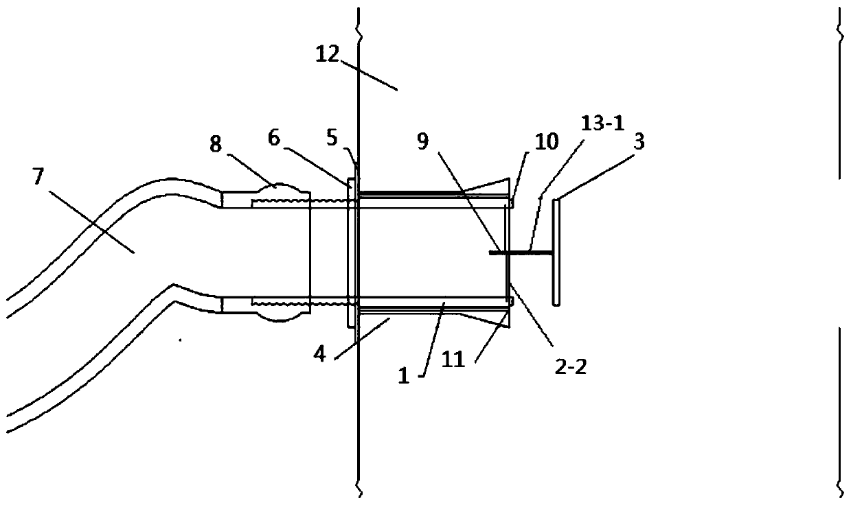
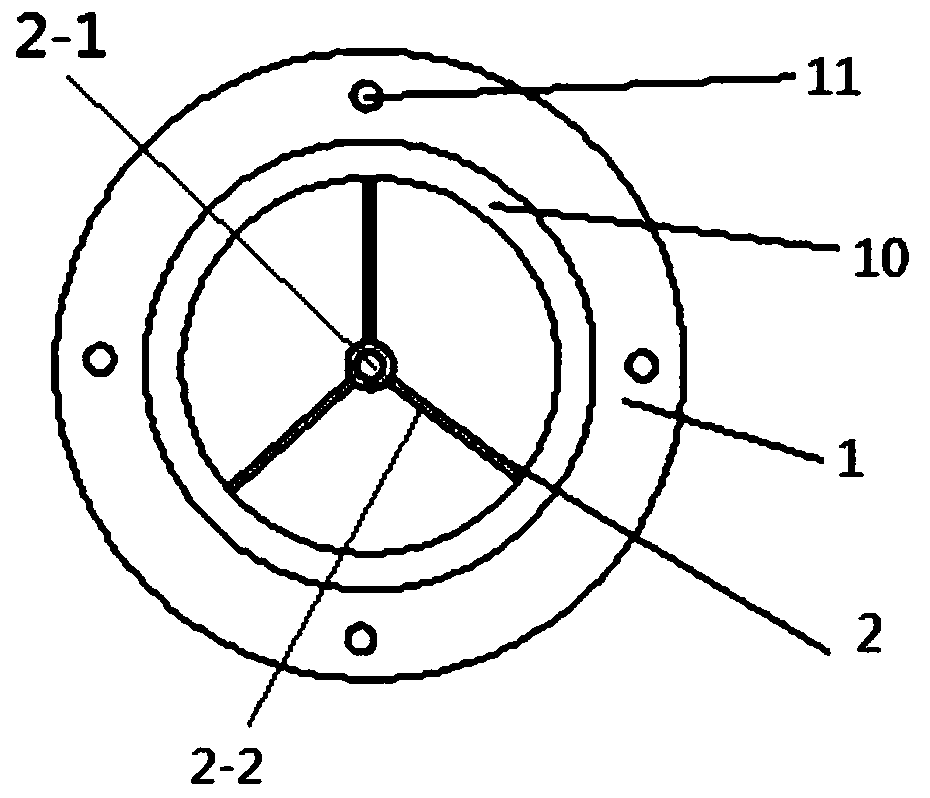
[0028] A grout stopper device for internal grouting of the present invention, such as figure 1 As shown, it includes: grout stop bolt 1, which is a cavity structure including a slurry inlet end and a slurry outlet end, and both ends are connected. Outside the grouting hole, the grouting end is located in the grouting hole; the inner diameter of the grouting bolt 1 is the same, and the outer wall of the grouting end of the grouting bolt 1 expands radially outward. On the premise that the grouting bolt 1 meets the requirement that the tear strength of the pipe wall is greater than the grouting pressure, the inner diameter can be increased as much as possible. The side wall of the slurry inlet end of the slurry stop bolt 1 is provided with an external thread.

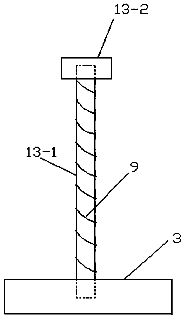
[0029] The grout stop cap 3 is a thin cylinder with a diameter greater than the inner diameter of the grout outlet end, which fits and is installed on the grout outlet end of the grout stop bolt 1, opens during grouting, ...


PUM


Abstract

The invention discloses an internal-connection-type grout-stopping plug for grouting, and a grouting method. The internal-connection-type grout-stopping plug comprises a grout-stopping bolt, a grout-stopping cap, a connecting device and a triangular frame vertical rib; the grout-stopping bolt is of a cavity structure comprising a grout inlet end and a gout outlet end, wherein the two ends of the cavity structure communicate with each other, the cavity is used for delivering grout, the grout-stopping bolt is used for being arranged in a grouting hole, the grout inlet end is located outside the grouting hole, and the gout outlet end is located in the grouting hole; the grout-stopping cap is a thin cylinder, the diameter of the grout-stopping cap is greater than the inner diameter of the grout outlet end, the grout-stopping cap is mounted at the grout outlet end of the grout-stopping bolt, and the grout-stopping cap is opened during grouting and closed when grouting is completed; the connecting device is detachably connected with one wall surface of the grout-stopping cap and located in the cavity of the grout-stopping bolt, the triangular frame vertical rib is axially arranged in the cavity of the grout-stopping bolt and connected with the connecting device, under the effects of the pressure of grout in the cavity of the grout-stopping bolt or the pressure of the grouting hole, the triangular frame vertical rib is matched with the connecting device to drive the grout-stopping cap to be correspondingly opened or closed. By using the internal-connection-type grout-stopping plug, automatic grout stopping can be effectively achieved.

Description

technical field [0001] The invention belongs to the technical field of pre-grouting engineering construction, and in particular relates to a grout stopper device and a grouting method for internally connected grouting. Background technique [0002] The grout stoppers used in the field of pre-grouting engineering construction mostly use internal grout stoppers to stop the grout. The traditional grout stoppers have strict requirements on the grouting slurry due to the insufficient diameter of the grout stoppers, and cannot automatically stop the grout. For grouting, valves are often used to stop grouting or sacks are blocked after disassembly, which can easily cause problems such as insufficient grouting strength, insufficient pressure or non-compactness, poor sealing apparent quality, and long cycle time; with the rapid development of engineering construction technology With the further improvement of development and construction quality requirements, the construction of pre-...

Claims


Application Information

Patent Timeline
Patent Type & Authority Applications(China)
IPC IPC(8): E02D3/12E02D15/04
CPCE02D3/12E02D15/04
Inventor 李博文李宁
Owner 李博文
Why Eureka
Try Eureka