Rotary locking quick docking device

A docking device and fast technology, applied in the direction of connecting components, mechanical equipment, etc., to achieve the effect of fast separation

Active Publication Date: 2019-09-17
ZHEJIANG AOCHUAN HYDRAULIC
View PDF6 Cites 8 Cited by
  • Summary
  • Abstract
  • Description
  • Claims
  • Application Information

AI Technical Summary

Problems solved by technology

[0002] For example, the publication number CN108942154A name is a kind of fast docking device of rotary locking pin type aerospace system sensor, a kind of fast docking device of sensor, more specifically, it is a kind of fast docking device of rotary locking pin type aerospace system sensor, including sensor docking mechanism , a positioning mechanism and a rotating locking pin. The sensor docking mechanism includes a sensor docking body, a sensor docking block and a mounting hole. The sensor docking blocks are fixedly connected to the four surfaces of the sensor docking body, and the four sensor docking blocks are fixedly connected. Mounting hole; the rotating locking pin includes a rota

Method used


Image

  • Rotary locking quick docking device
  • Rotary locking quick docking device
  • Rotary locking quick docking device

Examples


specific Embodiment approach 1

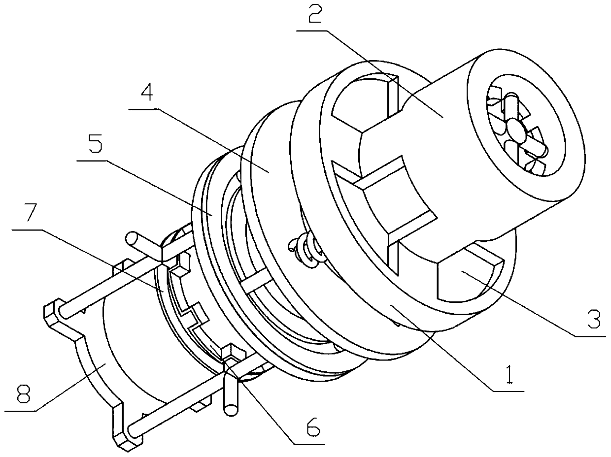
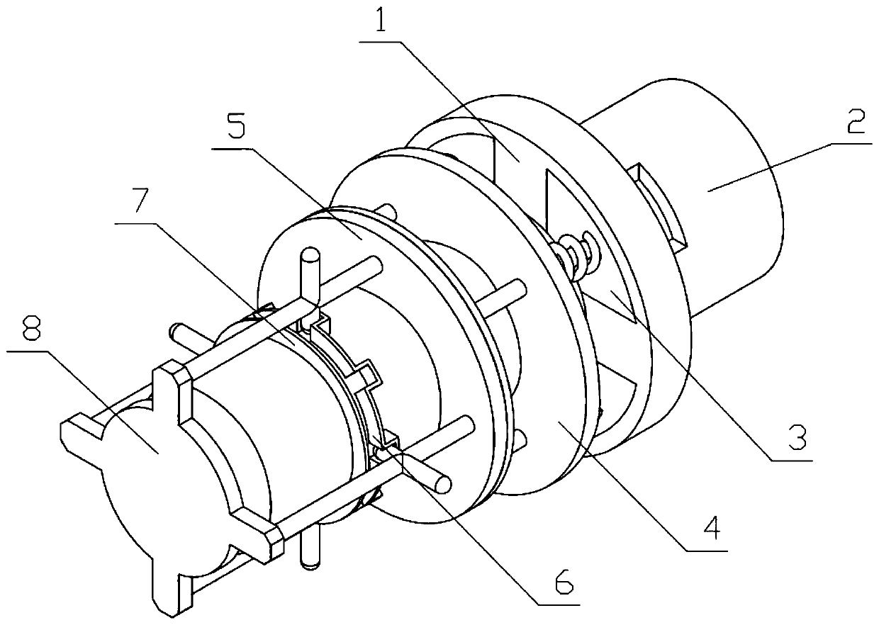
[0036] Combine below Figure 1-15Describe this embodiment, a quick docking device for rotation and locking, including a connecting frame I1, a connecting frame II2, a locking frame 3, a support ring 4, a sliding mechanism 5, a snap ring 6, a limit ring 7 and a disassembly mechanism 8, The connecting frame II2 is clamped on the connecting frame I1, the support ring 4 is fixedly connected to the connecting frame I1, the locking frame 3 is slidably connected to the supporting ring 4, and a compression spring is arranged between the locking frame 3 and the supporting ring 4 , the locking frame 3 is slidably connected to the connecting frame Ⅰ1 to limit the rotation of the connecting frame Ⅱ2, the sliding mechanism 5 is gap-fitted on the connecting frame Ⅰ1, the lower end of the locking frame 3 is rotatably connected to the sliding mechanism 5, and the snap ring 6 and the limiting The positioning rings 7 are all fixedly connected to the connecting frame I1, a dismounting slideway i...

specific Embodiment approach 2

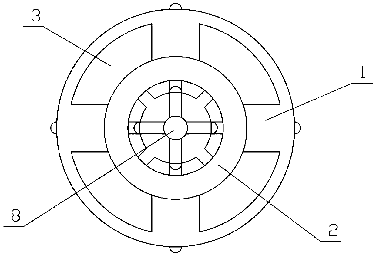
[0038] Combine below Figure 1-15 Describe this embodiment, this embodiment will further explain the first embodiment, the connecting frame I1 includes a connecting column 1-1, a connecting ring 1-2, a connecting baffle I1-3, a connecting baffle II1-4, and a clamping groove 1-5 and connecting slot 1-6, the lower end of the inner side of the connecting ring 1-2 is evenly fixed and connected in the circumferential direction with four connecting baffles Ⅰ1-3, and the inner sides of the four connecting baffles Ⅰ1-3 are all fixedly connected to the connecting column On 1-1, the upper end of the inner side of the connecting ring 1-2 is evenly fixed and connected in the circumferential direction with four connecting baffles II1-4, the connecting ring 1-2, four connecting baffles I1-3 and four connecting baffles II1- Four clamping grooves 1-5 are formed between 4, and connection clamping grooves 1-6 are formed between the four connecting baffles I1-3 and the four connecting baffles II...

specific Embodiment approach 3

[0040] Combine below Figure 1-15 Describe this embodiment, this embodiment will further explain the second embodiment, the connecting frame II 2 includes a connecting cylinder 2-1, a stop shoulder 2-2, a connecting board 2-3, a connecting clamping board 2-4 and Disassemble the push block 2-5, the upper end of the inner side of the connecting cylinder 2-1 is provided with a stop shoulder 2-2, and the lower end of the connecting cylinder 2-1 is uniformly fixed and connected in the circumferential direction with four connecting plates 2-3, and the four connecting plates 2-3 The outer side of the lower end of the plugboard 2-3 is fixedly connected with a connection clamp 2-4, and the four connection clamps 2-4 are respectively stuck in the four connection clamp grooves 1-6, and the inner circumference of the stop shoulder 2-2 There are eight dismounting push blocks 2-5 that are uniformly fixedly connected, and eight dismounting push grooves are formed between the eight dismountin...


PUM


Abstract

The invention relates to a docking device, in particular to a rotary locking quick docking device. The rotary locking quick docking device comprises a connecting frame I, a connecting frame II, a locking frame, a supporting ring, a sliding mechanism, a snap ring, a limiting ring and a dismounting mechanism; the connecting frame II is clamped to the connecting frame I, the supporting ring is fixedly connected to the connecting frame I, the locking frame is slidably connected to the supporting ring, and a compression spring is arranged between the locking frame and the supporting ring; a connecting clamping plate can be rotated while the connecting clamping plate is made move downwards, the connecting clamping plate accordingly presses a arc baffle to clamp the arc baffle into a connecting clamping slot, and quick connection of the connecting frame I and the connecting frame II is completed; the arc baffle resets under the action of the compression spring, the locking frame is slidably connected to the connecting frame I to conduct rotation limiting on the connecting frame II, and the connecting frame II is completely clamped to the connecting frame I; and the connecting frame I and the connecting frame II are locked in one direction, the connecting frame I can be separated from the connecting frame II only by moving the sliding mechanism on the connecting frame I.

Description

technical field [0001] The invention relates to a docking device, in particular to a fast docking device with rotation and locking. Background technique [0002] For example, the publication number CN108942154A name is a kind of fast docking device of rotary locking pin type aerospace system sensor, a kind of fast docking device of sensor, more specifically, it is a kind of fast docking device of rotary locking pin type aerospace system sensor, including sensor docking mechanism , a positioning mechanism and a rotating locking pin. The sensor docking mechanism includes a sensor docking body, a sensor docking block and a mounting hole. The sensor docking blocks are fixedly connected to the four surfaces of the sensor docking body, and the four sensor docking blocks are fixedly connected. Mounting hole; the rotating locking pin includes a rotating baffle and a rotating column, which can be passed through the mounting hole provided on the sensor docking block by rotating the ro...

Claims


Application Information

Patent Timeline
IPC IPC(8): F16B21/02
CPCF16B21/02
Inventor 李忠吉
Owner ZHEJIANG AOCHUAN HYDRAULIC
Why Eureka
Try Eureka