

Side buckled modular connector
A connector and snap-fit technology, which is applied to the connection, parts of the connection device, coupling device, etc., can solve the problems of poor process consistency, low production efficiency, and difficult detection, and achieve good assembly consistency and high production efficiency , good detectability
- Summary
- Abstract
- Description
- Claims
- Application Information
AI Technical Summary
Problems solved by technology
Method used
Image

Examples
Embodiment Construction
[0038] In order to further illustrate the technical solutions adopted by the present invention to achieve the intended purpose, the following will be further described in detail in conjunction with the accompanying drawings and preferred embodiments.
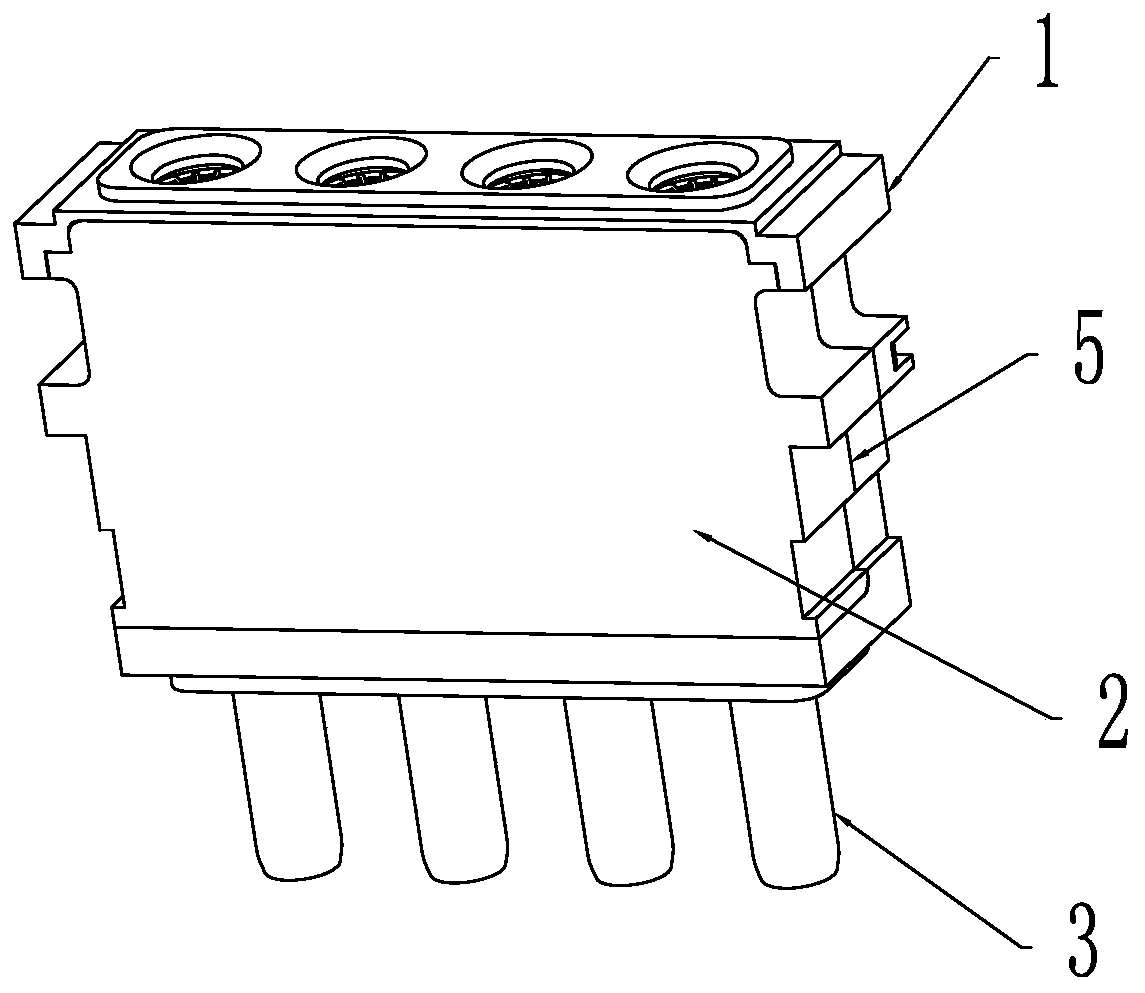
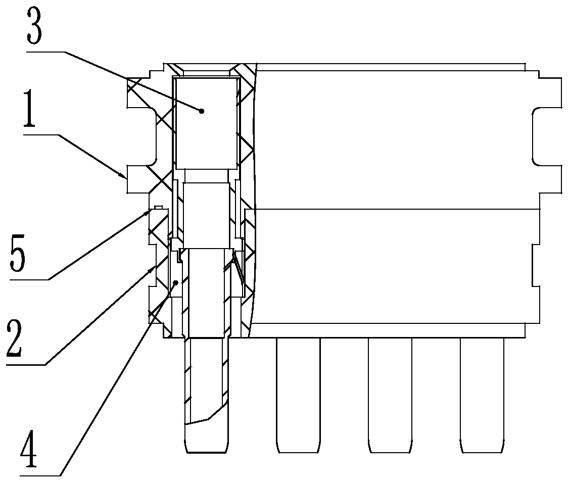
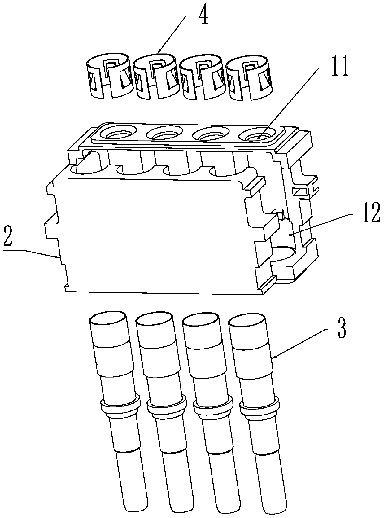
[0039] see Figure 2 to Figure 3 , a side snap-fit modular connector of the present invention, including an insulator 1, an insulating pressing plate 2, a contact 3 and a positioning spring 4, and the insulating pressing plate 2 is buckled on the side of the insulator 1 and forms at least one inside the insulator for contacting The mounting hole 11 through which the part 3 is worn and fits with the contact part 3 in a gap, the positioning spring 4 is arranged in the mounting hole 5, and the positioning spring 4 and the positioning boss 12 provided on the top of the insulator 1 jointly carry out the contact part 3 Axial limit.
[0040] Further, the joint surface 5 formed after the insulating pressing plate 2 is buckled with th...
PUM
 Abstract
Description
Claims
Application Information