Supercharge Your Innovation With Domain-Expert AI Agents!

Electric connector assembly

A technology of electrical connectors and electrical connections, which is applied in the direction of connection, parts of connection devices, electrical components, etc., which can solve the problems of the influence of electrical systems, the inability of metal shells to completely surround terminals, etc., and achieve the effect of preventing electromagnetic interference

Inactive Publication Date: 2019-09-17
DEYI PRECISION ELECTRONIC IND CO LTD PANYU
View PDF5 Cites 0 Cited by
  • Summary
  • Abstract
  • Description
  • Claims
  • Application Information

AI Technical Summary

Problems solved by technology

[0004] The existing electrical connector assembly includes a substrate and an electrical connector arranged on the substrate. The electrical connector includes an insulating body, a plurality of terminals disposed in the insulating body, and a metal shell for receiving the insulating body to provide electromagnetic shielding. , where the pins of the terminals are DIP pins, that is, the pins of the terminals pass through the substrate to form an electrical connection, so the metal shell must not completely surround the terminals, that is, a part of the terminals must be exposed outside the metal shell
With the development of technology, due to the increasingly high frequency of signals transmitted by terminals and the compact arrangement of various electrical components brought about by the miniaturization of equipment, the electromagnetic interference leaked by terminal pins can no longer be ignored. It will have adverse effects on the entire electrical system in which the electrical connector assembly is applied

Method used


Image

  • Electric connector assembly
  • Electric connector assembly
  • Electric connector assembly

Examples


Embodiment Construction

[0048] In order to facilitate a better understanding of the purpose, structure, features, and effects of the present invention, the present invention will now be further described in conjunction with the accompanying drawings and specific embodiments.

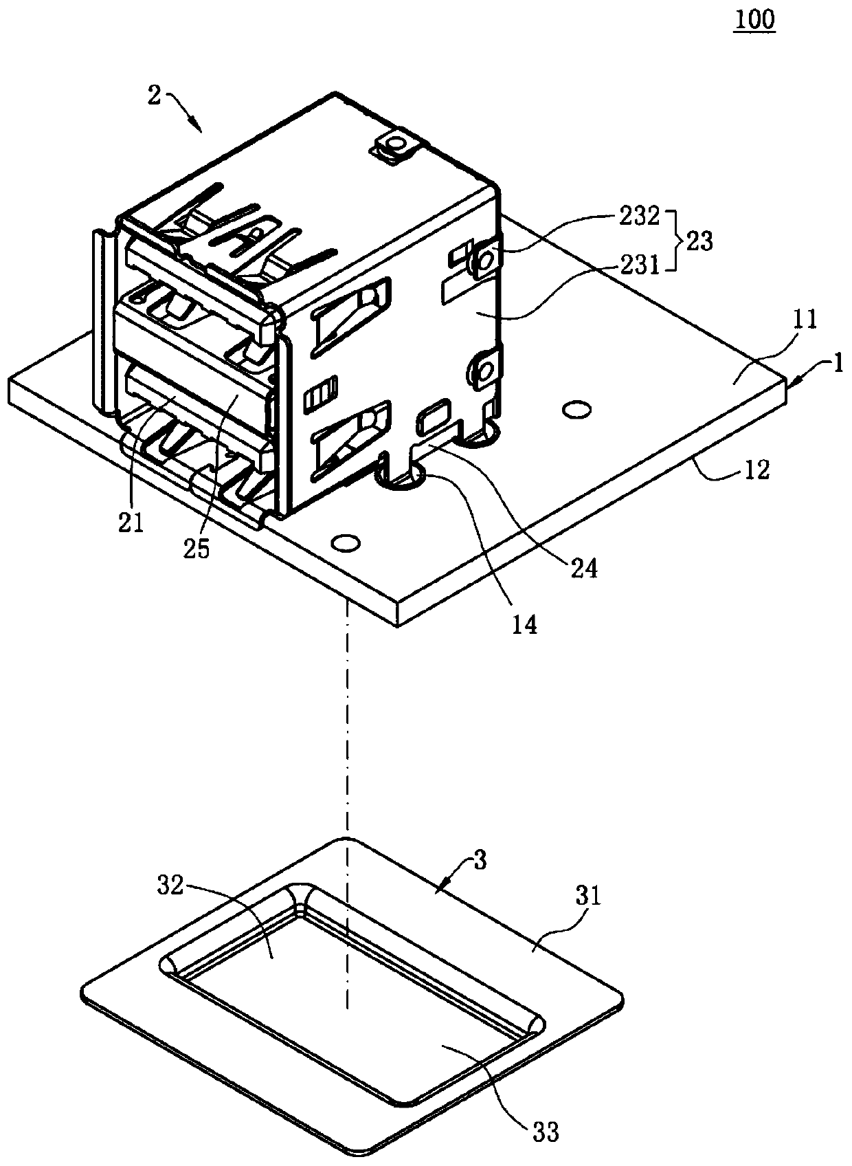
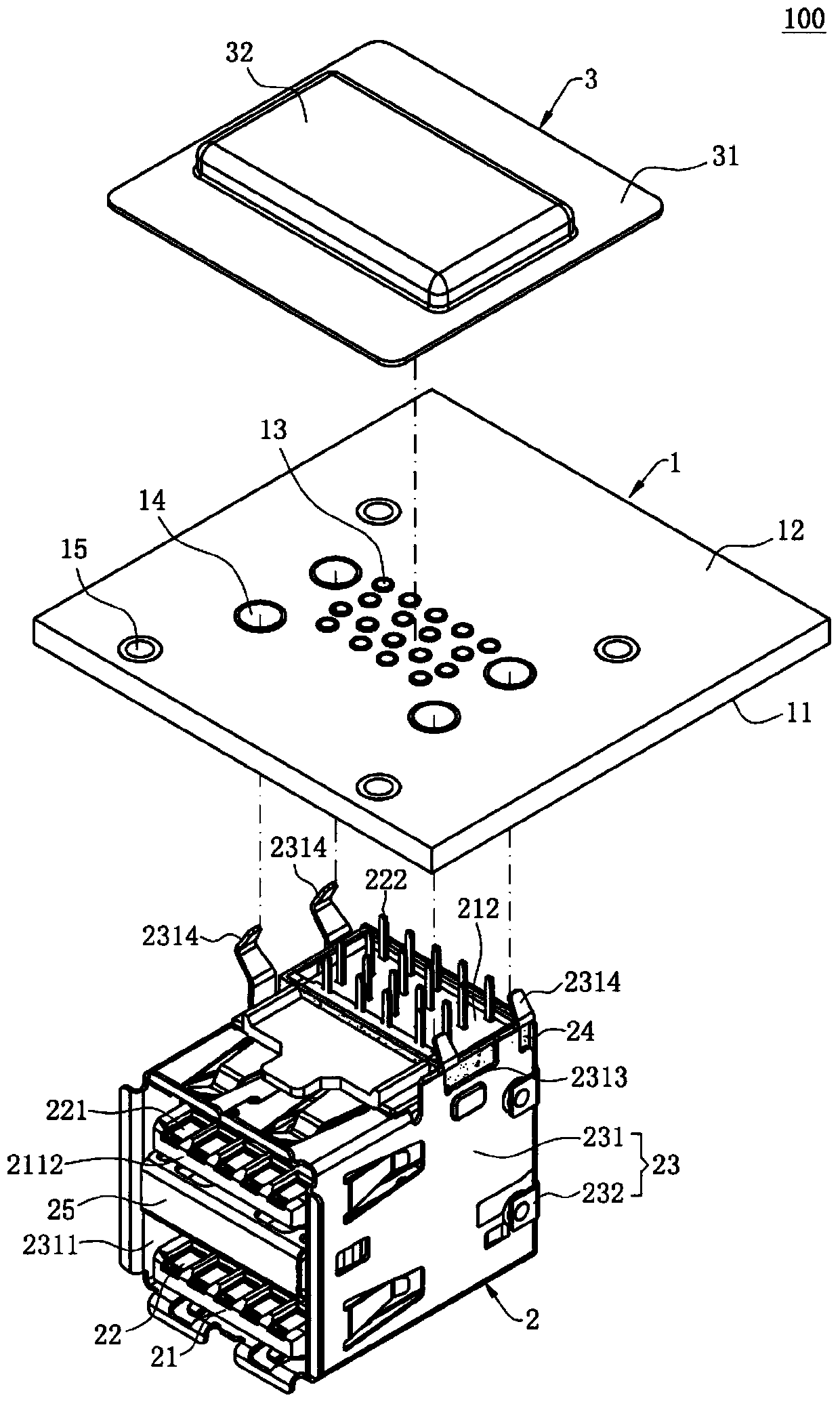
[0049] Such as Figure 1 to Figure 7 Shown is the first embodiment of the electrical connector assembly 100 of the present invention, which includes a circuit board 1 , an electrical connector 2 and a shielding member 3 mounted on the circuit board 1 .

[0050] Such as figure 1 and figure 2 As shown, the circuit board 1 has a first surface 11 and a second surface 12 disposed opposite to the first surface 11, the electrical connector 2 is mounted on the first surface 11, and the shielding member 3 is installed on the second surface 12, in the embodiment, the first surface 11 is the upper surface of the circuit board 1, and the second surface 12 is the lower surface of the circuit board 1. The circuit board 1 also has a plura...


PUM


Abstract

The invention discloses an electric connector assembly comprising a circuit board which comprises a first surface, a second surface and a plurality of first through holes which are communicated with the first surface and the second surface; an electric connector which comprises an insulating body located on the first surface and a plurality of conductive terminals arranged on the insulating body, wherein each conductive terminal is provided with a conductive connection part, the conductive connection parts penetrate through the first surface to enter the corresponding first through holes. The electric connector further comprises a shielding shell for accommodating the insulating body; a shielding piece, located on a second surface for shielding the plurality of conductive connection parts and being electrically isolated from the conductive connection parts. The shielding piece and the shielding shell are electrically connected with each other to form grounding; the shielding piece located on the second surface of the circuit board shields the plurality of conductive connection parts of the plurality of conductive terminals and prevents the conductive connection parts from leaking electromagnetic interference, and the shielding piece and the shielding shell are electrically connected with each other and grounded, so that the shielding piece and the shielding shell can jointly form relatively complete electromagnetic shielding for the conductive terminals.

Description

[0001] 【Technical field】 [0002] The invention relates to an electrical connector assembly, in particular to an electrical connector assembly for preventing electromagnetic interference. [0003] 【Background technique】 [0004] The existing electrical connector assembly includes a substrate and an electrical connector arranged on the substrate. The electrical connector includes an insulating body, a plurality of terminals disposed in the insulating body, and a metal shell for receiving the insulating body to provide electromagnetic shielding. , wherein the pins of the terminals are DIP pins, that is, the terminal pins pass through the substrate to form an electrical connection, so the metal shell must not completely surround the terminals, that is, a part of the terminals must be exposed outside the metal shell. With the development of technology, due to the increasingly high frequency of signals transmitted by terminals and the compact arrangement of various electrical compon...

Claims


Application Information

Patent Timeline
Patent Type & Authority Applications(China)
IPC IPC(8): H01R13/6594
CPCH01R13/6594
Inventor 陈志坤沈昌泰
Owner DEYI PRECISION ELECTRONIC IND CO LTD PANYU
Features
  • R&D
  • Intellectual Property
  • Life Sciences
  • Materials
  • Tech Scout
  • Unparalleled Data Quality
  • Higher Quality Content
  • 60% Fewer Hallucinations
Learn More