Camera optical center testing method

A test method and camera technology, applied in the field of camera detection, can solve problems such as inaccurate camera module testing

Inactive Publication Date: 2019-09-17
广州聚美视觉科技有限公司
View PDF8 Cites 0 Cited by
  • Summary
  • Abstract
  • Description
  • Claims
  • Application Information

AI Technical Summary

Problems solved by technology

[0004] The technical problem to be solved by the present invention is to provide a camera optical center test method, which solves the problem of inaccurate camera module testing

Method used


Image

  • Camera optical center testing method
  • Camera optical center testing method
  • Camera optical center testing method

Examples


Embodiment Construction

[0024] The specific embodiments of the present invention will be further described below in conjunction with the accompanying drawings. It should be noted here that the descriptions of these embodiments are used to help understand the present invention, but are not intended to limit the present invention. In addition, the technical features involved in the various embodiments of the present invention described below may be combined with each other as long as they do not constitute a conflict with each other.

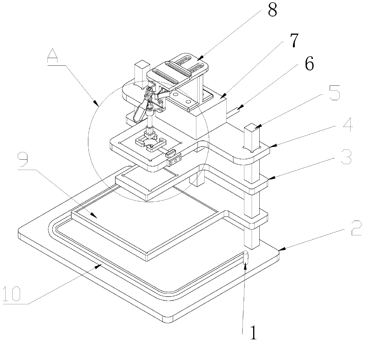
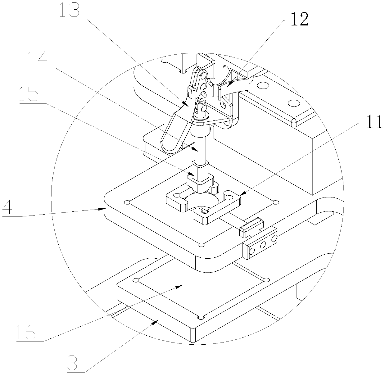
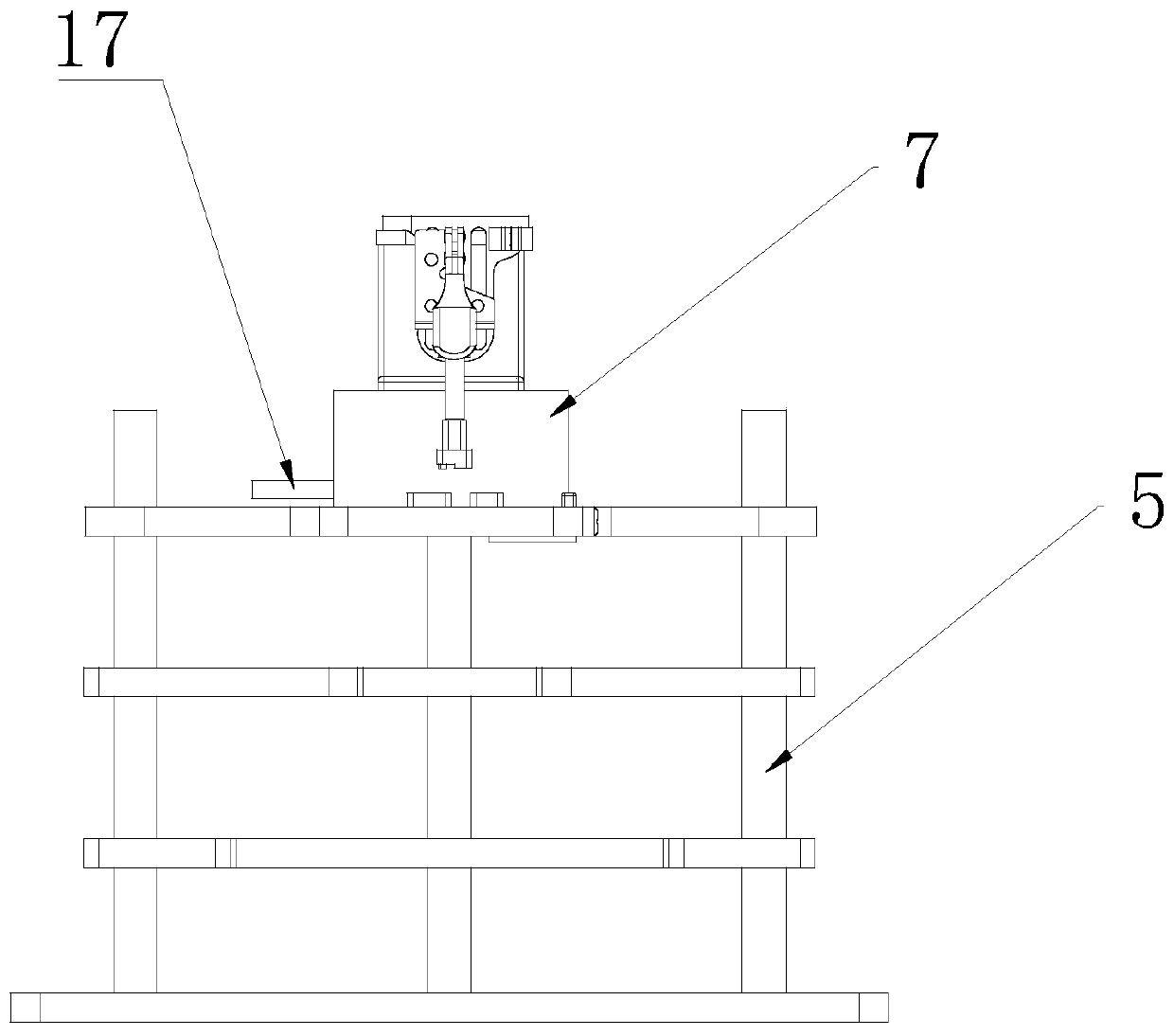
[0025] refer to Figure 1 to Figure 4 , a kind of camera optical center testing method provided by the present invention, comprises the following steps:

[0026] Step 1: get ready test frame and TV microscope (not shown in the figure), described test frame comprises base 2, and described base 2 front side is provided with slide rail 10, and described TV microscope is placed on described slide rail 10 , the rear end of the upper end surface of the base 2 is provided wit...


PUM


Abstract

The invention discloses a camera optical center testing method. The method comprises the following steps: preparing a test frame and a TV microscope; arranging the LED panel fixing plate, the test Chart diagram fixing plate and the module fixing plate horizontally; placing an LED panel on the LED panel fixing plate, placing a test Clart chart in the test Clart chart placing hole, placing the module in the module fixing support, and pressing the module down through tightly the rapid pressing mechanism; starting a light source of the LED panel, sliding the TV microscope to a designated position, observing and testing the cross curve of the center of the Clart image, the optical center of the lens group and the center of the chip, and judging whether the product is qualified or not; and after detection, resetting the rapid pressing mechanism and the TV microscope, and taking out and placing the tested module at a designated position. According to the invention, the test frame is adopted to fix the module, test the Clart chart and the LED panel light source, and test whether the module is qualified or not through the TV microscope; the test method is simple, convenient to operate and accurate in detection, and solves the problem that the module test of the camera is inaccurate.

Description

technical field [0001] The invention relates to the technical field of camera detection, in particular to a method for testing the optical center of a camera. Background technique [0002] The module of the car camera needs to ensure that the optical center of the camera and the center of the chip are coincident during actual shooting, so that there will be no visual difference in actual application. If the imaging of the module is actually in a certain direction when shooting Yes, in actual application, it will cause visual differences and easily cause safety hazards. Therefore, the camera must pass the qualification test. When the module is assembled, it is enough to check that the overall parts are installed and meet the requirements of the test. [0003] During the assembly process of the module, the assembly tolerance and other factors will cause the optical center of the lens to deviate from the center of the chip, resulting in defective products such as dark corners ...

Claims


Application Information

Patent Timeline
IPC IPC(8): H04N17/00
CPCH04N17/002
Inventor 范莉
Owner 广州聚美视觉科技有限公司
Why Eureka
Try Eureka