Fish pond feed casting device
A feed and fish pond technology, which is applied in the field of fish pond feed thrower, can solve the problems of inconvenient adjustment of throwing distance and angle, and feed cannot be operated for a long time, so as to achieve the effect of easy adjustment, improved stability and long-lasting throwing
- Summary
- Abstract
- Description
- Claims
- Application Information
AI Technical Summary
Problems solved by technology
Method used
Image

Examples
Embodiment 1
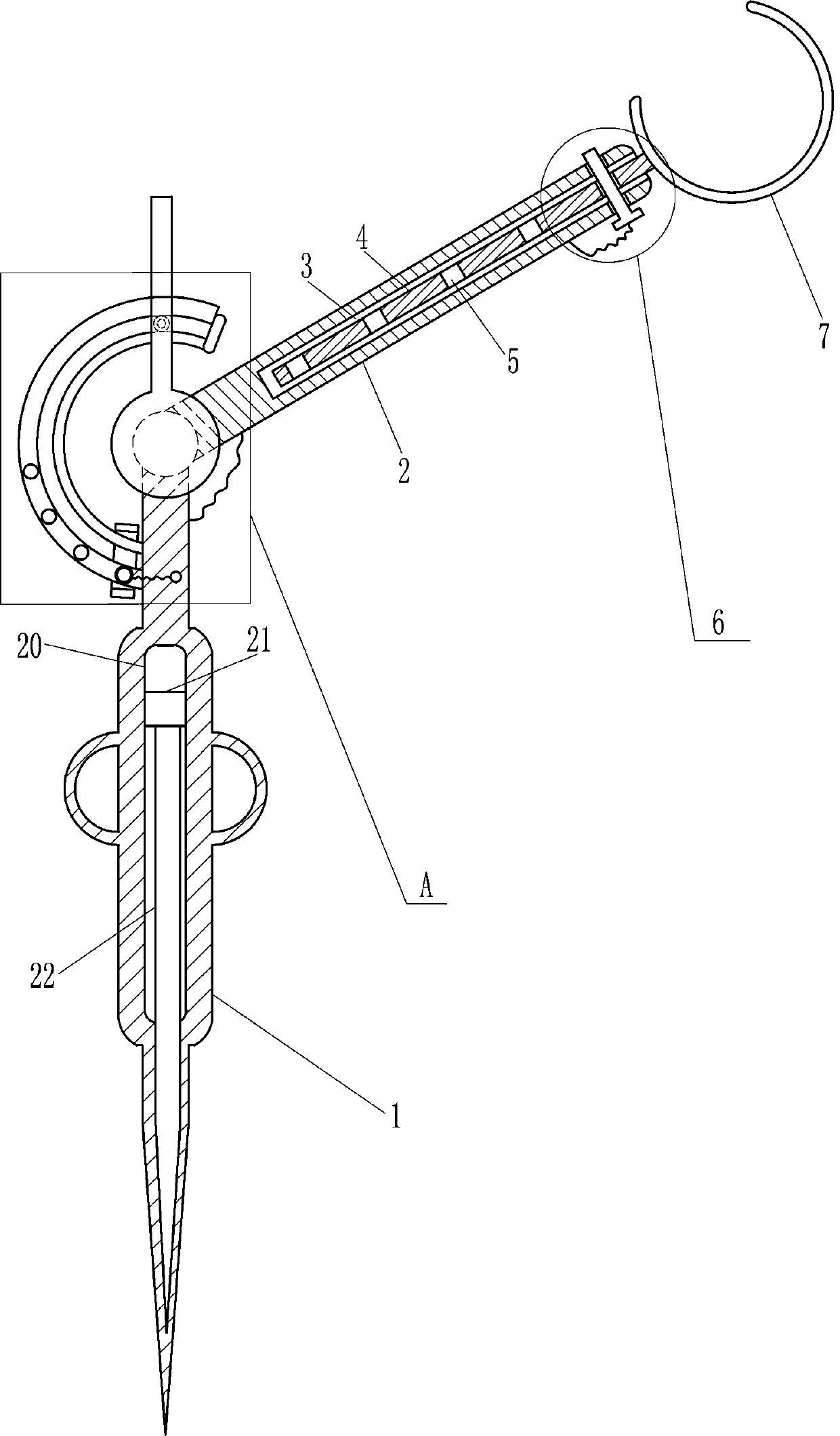
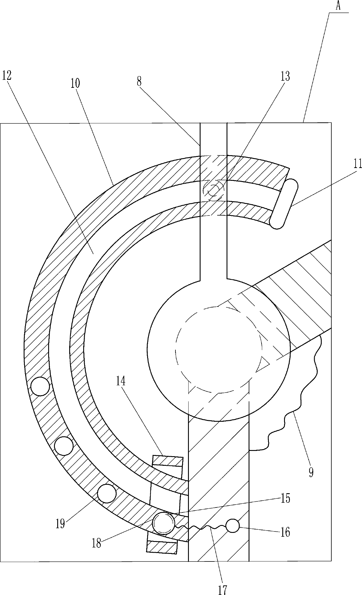
[0016] A kind of fish pond feed thrower, such as Figure 1-3 As shown, it includes a tapered column 1, a swing bar 2, a moving bar 4, a dismounting mechanism 6, a U-shaped frame 7, a grip bar 8 and a spring 9, and the top of the tapered column 1 is connected with a swing bar 2 in a rotating manner, and the tapered column A spring 9 is connected between the upper right side of the swing rod 2 and the lower right side of the swing rod 2, the tapered column 1 and the swing rod 2 are connected to the spring 9 by welding, the swing rod 2 has a groove 3 inside, and the groove 3 The inner sliding type is provided with a moving rod 4, and a plurality of first threaded holes 5 are evenly opened on the moving rod 4. A disassembly mechanism 6 is installed on the upper part of the swing rod 2, and the disassembly mechanism 6 is connected with the moving rod 4. The upper end of the moving rod 4 is provided with a U Shaped frame 7, moving bar 4 is connected with U-shaped frame 7 by the mode...
Embodiment 2
[0018] A kind of fish pond feed thrower, such as Figure 1-3 As shown, it includes a tapered column 1, a swing bar 2, a moving bar 4, a dismounting mechanism 6, a U-shaped frame 7, a grip bar 8 and a spring 9, and the top of the tapered column 1 is connected with a swing bar 2 in a rotating manner, and the tapered column A spring 9 is connected between the upper part on the right side and the lower part on the right side of the swing bar 2. There is a groove 3 in the swing bar 2. A sliding rod 4 is provided in the groove 3. A plurality of first A threaded hole 5, a dismantling mechanism 6 is installed on the fork 2 top, and the dismantling mechanism 6 is connected with the moving bar 4, and the moving bar 4 upper end is provided with a U-shaped frame 7, and the front side of the fork 2 lower end is connected with a grip bar 8.
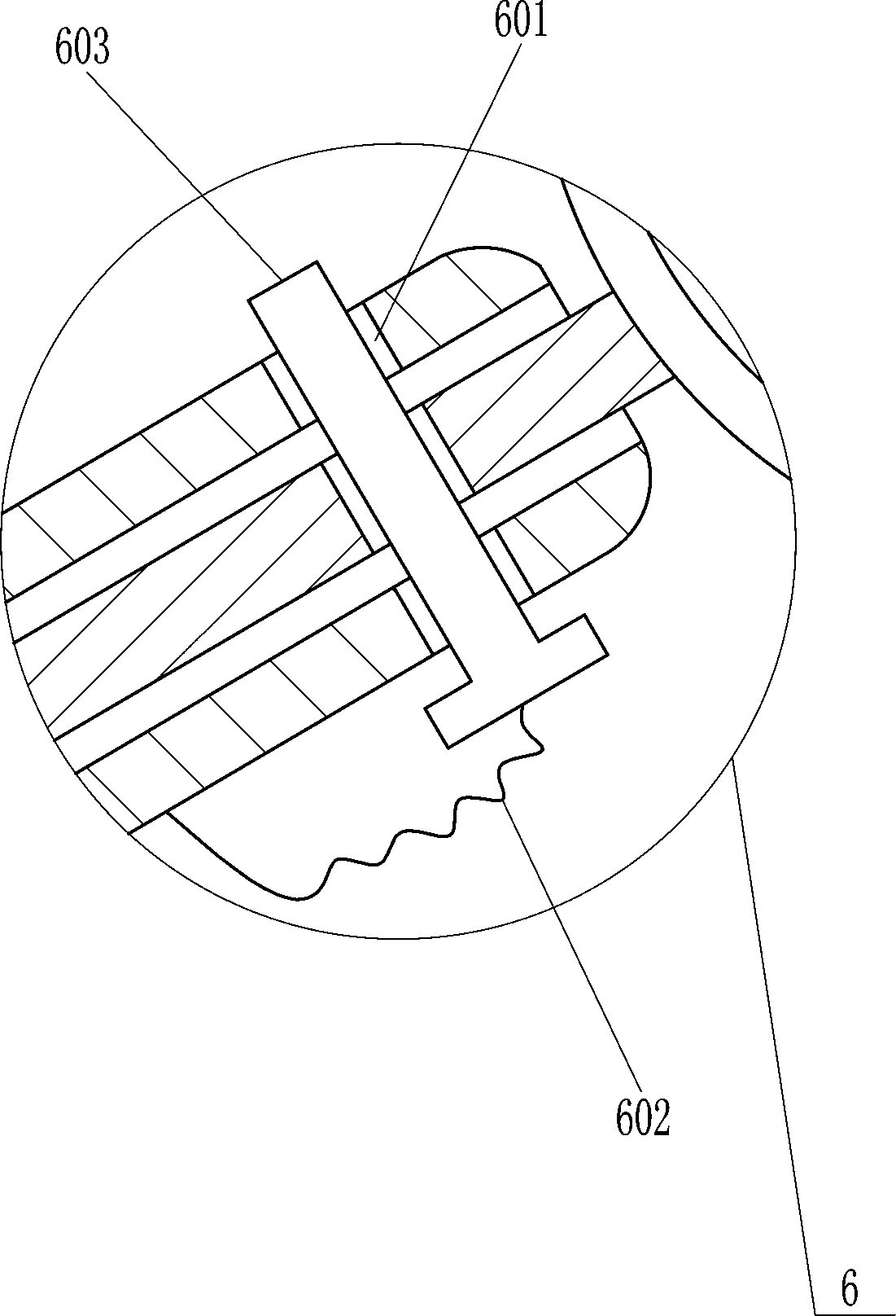
[0019] The dismantling mechanism 6 includes a first connecting rope 602 and a first bolt 603. The upper and lower sides of the upper end of the swing ...
Embodiment 3
[0021] A kind of fish pond feed thrower, such as Figure 1-3 As shown, it includes a tapered column 1, a swing bar 2, a moving bar 4, a dismounting mechanism 6, a U-shaped frame 7, a grip bar 8 and a spring 9, and the top of the tapered column 1 is connected with a swing bar 2 in a rotating manner, and the tapered column A spring 9 is connected between the upper part on the right side and the lower part on the right side of the swing bar 2. There is a groove 3 in the swing bar 2. A sliding rod 4 is provided in the groove 3. A plurality of first A threaded hole 5, a dismantling mechanism 6 is installed on the fork 2 top, and the dismantling mechanism 6 is connected with the moving bar 4, and the moving bar 4 upper end is provided with a U-shaped frame 7, and the front side of the fork 2 lower end is connected with a grip bar 8.
[0022] The dismantling mechanism 6 includes a first connecting rope 602 and a first bolt 603. The upper and lower sides of the upper end of the swing ...
PUM
 Abstract
Description
Claims
Application Information
 - R&D
- Intellectual Property
- Life Sciences
- Materials
- Tech Scout
- Unparalleled Data Quality
- Higher Quality Content
- 60% Fewer Hallucinations
Browse by: Latest US Patents, China's latest patents, Technical Efficacy Thesaurus, Application Domain, Technology Topic, Popular Technical Reports.
© 2025 PatSnap. All rights reserved.Legal|Privacy policy|Modern Slavery Act Transparency Statement|Sitemap|About US| Contact US: help@patsnap.com