Sand screening device for bridge construction

A sand sieve and bridge technology, which is applied in the direction of sieving, solid separation, dry gas arrangement, etc., can solve the problems of sieve hole clogging, insufficient dispersion of sand, and low sieving efficiency, and achieve full sieving , Improve the screening efficiency and promote the volatilization of water

Inactive Publication Date: 2019-09-20
赣州市兴顺辉科技有限公司
View PDF8 Cites 14 Cited by
  • Summary
  • Abstract
  • Description
  • Claims
  • Application Information

AI Technical Summary

Benefits of technology

This technology improves the quality control for fine-grained materials like silica gel powder during manufacture processes. It allows for better distribution over multiple layers of material before it reaches its final destination or use after being shipped out from production facilities. By repeating turning the sand back many times while heating it at high temperatures, this process helps evaporating any remaining moisture content without damaging them. Additionally, there'll be an improvement in the separation performance when driving the sand towards another direction called perpendicularly (up/down). Overall, these technical improvements help improve the overall productivity and purification capabilities of the resulting products.

Problems solved by technology

This patented describes an apparatus for efficiently separating out small particles from larger solid materials such as gravels during construction projects. However, this problem has been solved by providing a special type of equipment with screens made up of inclined bars arranged perpendicular to each other along its length. These screens help prevent blockages caused by these smaller solids while still allowing them through properly.

Method used


Image

  • Sand screening device for bridge construction
  • Sand screening device for bridge construction
  • Sand screening device for bridge construction

Examples


Embodiment 1

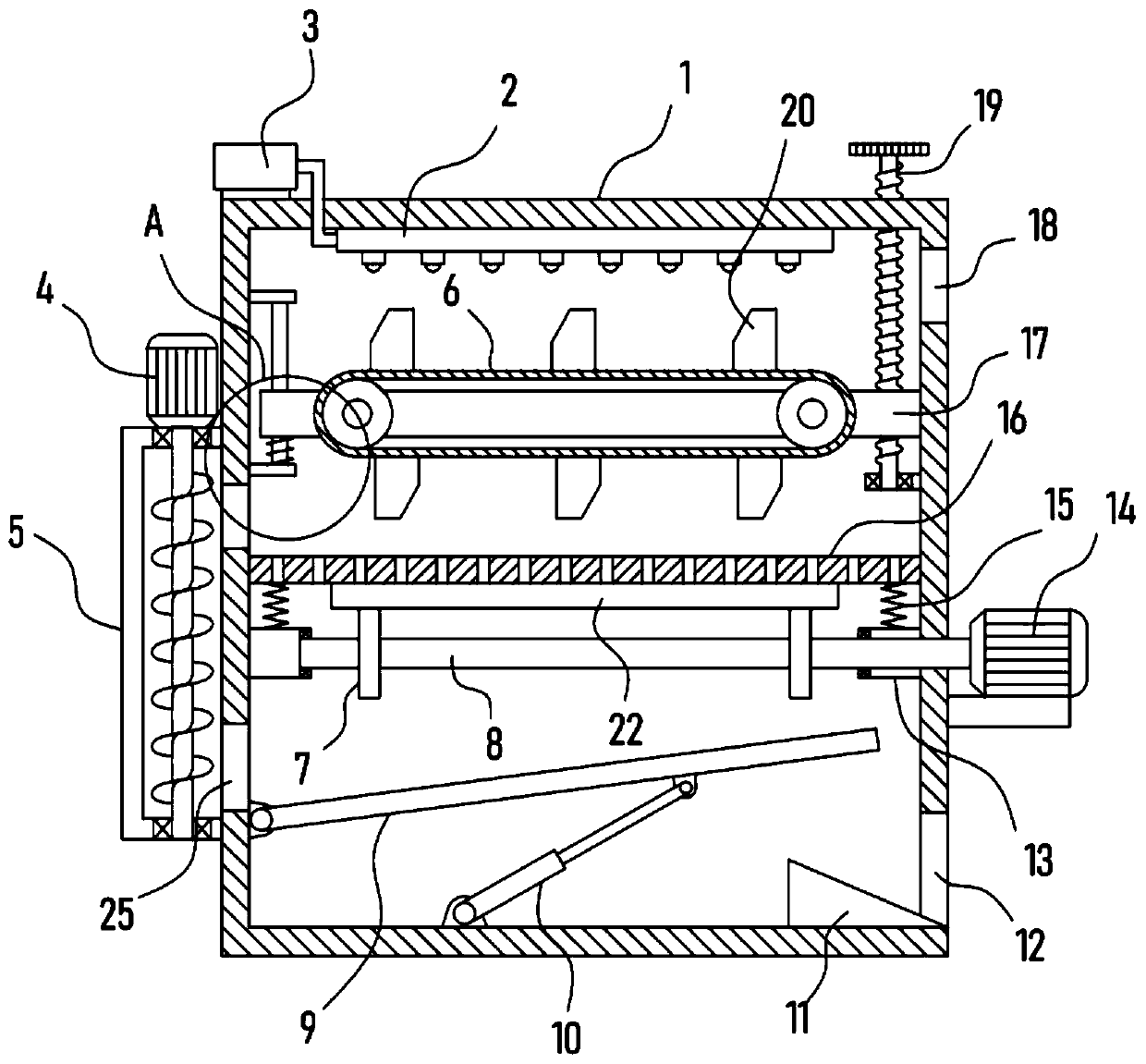
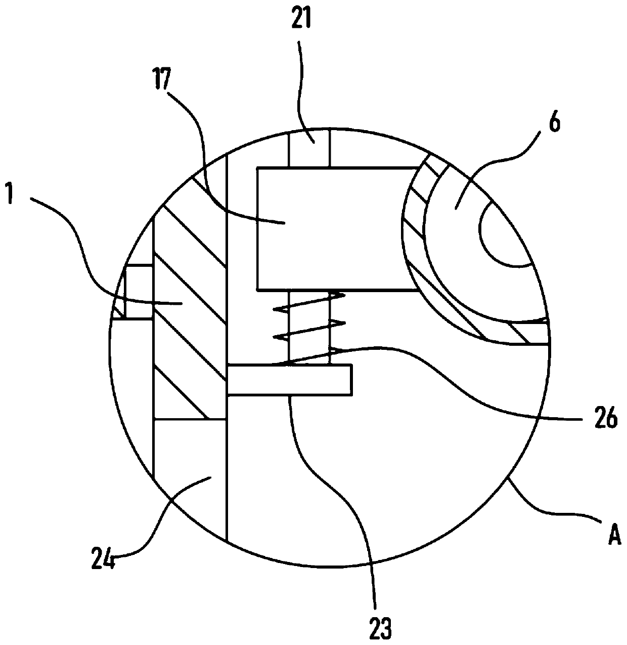
[0021] see Figure 1-3 , a sand screening device for bridge construction, comprising a screening box 1, a horizontally arranged sieve plate 16 is slidably installed in the screening box 1, and it is characterized in that a horizontal frame 17 is provided in the screening box 1, Rotate on the horizontal frame 17 and be provided with conveyor belt 6, the surface of conveyor belt 6 is evenly fixed with several sand taking tanks 20, and the drying mechanism vertically corresponding to conveyor belt 6 is fixed on the top of described screening box 1, and described sieve A servo motor II14 is fixed outside the sub-box 1, and the servo motor II14 is driven and connected with an exciting mechanism connected with the sieve plate 16 in transmission.

[0022] When screening the sand, the sand is placed on the sieve plate 16 in the screening box 1, and the relatively fine sand passes through the sieve holes to realize the screening and separation of the sand, and the rotation of the conve...

Embodiment 2

[0029] In order to further accelerate the sand screening efficiency of the screening box 1, on the basis of Embodiment 1, the vibration excitation mechanism includes a rotating shaft 8 coaxially fixed with the output shaft of the servo motor II14, and the surface of the rotating shaft 8 is evenly distributed in the circumferential direction. Several transmission blocks 7 are fixed, and the bottom of the sieve plate 16 is fixed with a convex line 22 abutting against the transmission blocks 7, and the sieve plate 16 is vertically slidingly connected with the screening box 1 through an elastic connection assembly.

[0030] The servo motor II14 is used to drive the rotating shaft 8 to realize its rotation, and the rotating shaft 8 drives the transmission block 7 on it to rotate, and the transmission block 7 and the convex strip 22 contact and drive to realize the sieve plate 16 under the elastic action of the elastic connection assembly. Vibrating up and down accelerates the vibrat...


PUM


Abstract

The invention discloses a sand screening device for bridge construction, and relates to the technical field of construction machinery. The sand screening device comprises a screening box, wherein a horizontal frame is arranged in the screening box, a conveying belt is rotationally arranged on the horizontal frame, a drying mechanism which vertically corresponds to the conveying belt is fixed at the inner top of the screening box, a servo motor II is fixedly arranged outside the screening box, and an excitation mechanism which is in transmission connection with a sieve plate is connected with the servo motor II in a driven mode. According to the sand screening device, before sand is screened, a sand fetching tank is driven by the conveying belt to repeatedly turn over the sand, so that the sand is more dispersed; meanwhile, an air injection disc in the drying mechanism is used for carrying out hot air drying on the sand dispersed on the conveying belt, so that the volatilization of water is promoted, the fluidity and the dispersion degree of the sand are higher, the screening efficiency is obviously improved, the excitation mechanism can achieve the up-and-down vibration effect of the sieve plate, it is guaranteed that the fine sand can be accelerated to pass through the sieve plate, and sand screening is more sufficient.

Description


Claims


Application Information

Patent Timeline
Owner 赣州市兴顺辉科技有限公司
Why Eureka
Try Eureka