A kind of riveting method of balance counterweight and riveting tooling

A technology of balancing counterweight and riveting tooling, applied in the field of mechanical assembly, can solve the problems of unstable riveting process, easy riveting failure, fatigue stress of fan disk, etc., and achieve the effect of improving the success rate of riveting, shortening the assembly cycle and good positioning performance.

Active Publication Date: 2020-11-06
AECC AVIATION POWER CO LTD
View PDF7 Cites 0 Cited by
  • Summary
  • Abstract
  • Description
  • Claims
  • Application Information

AI Technical Summary

Problems solved by technology

[0005] (1) The impact force of the pneumatic riveting gun is relatively large, and the adapter rod is easily broken, which makes the riveting work impossible
It is easy to hurt people if the pieces fly out. If the pieces fall into the inner cavity of the rotor assembly of the supercharger stage, it will cause the supercharger stage to be disassembled and troubleshoot, and there is a big risk hidden danger
[0006] (2) Pneumatic riveting gun cannot be positioned, it is difficult for personnel to operate, and the riveting gun head is easy to come off the adapter rod
[0007] (3) The riveting process is unstable and cannot achieve standardized operations
[0008] (4) During the riveting process, the rivet is easily bent or the size of the rivet head after riveting does not meet the requirements, and it needs to be removed and replaced
[0009] (5) When riveting, the impact force of the pneumatic riveting gun will be directly transmitted to the fan tray through the tooling, which may cause slight deformation of the fan tray or cause fatigue stress on the front mounting edge of the fan tray
[0010] Based on the above reasons, the method of riveting the rivet with the pneumatic riveting gun through the transfer rod takes a long time, the difference in personnel operation is large, the riveting result is unstable, the riveting failure is easy, and the removal of the riveting failed rivet is easy to scratch the installation edge of the fan tray, etc. , there are great risks and hidden dangers, which will affect the completion of engine production tasks and assembly cycle

Method used


Image

  • A kind of riveting method of balance counterweight and riveting tooling
  • A kind of riveting method of balance counterweight and riveting tooling
  • A kind of riveting method of balance counterweight and riveting tooling

Examples


Embodiment Construction

[0038] The present invention is described in further detail below in conjunction with accompanying drawing:

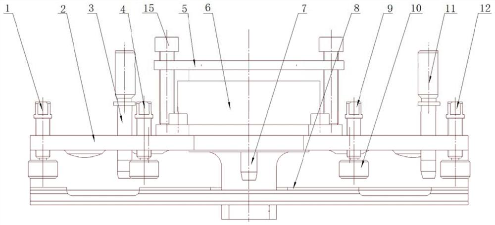
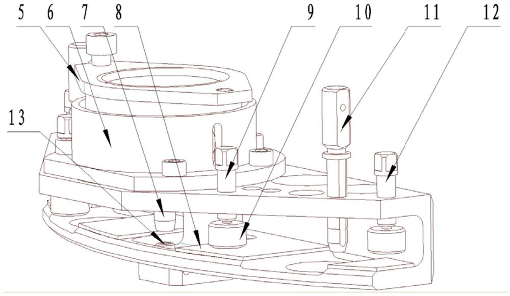
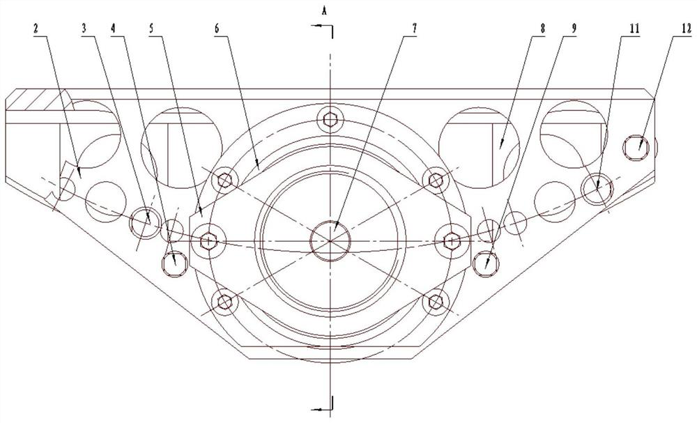
[0039] Such as Figure 1 to Figure 4 As shown, a balance weight riveting tooling includes a bow-shaped clamp block 2. The U-shaped groove structure in the middle of the bow-shaped clamp block 2 matches the front surface of the fan disk. The two sides of the bow-shaped clamp block 2 are the upper end wall and the lower end wall respectively. The upper end wall of the clamp block 2 is provided with a through hole perpendicular to the upper end wall, and the upper side of the upper end wall of the bow-shaped clamp block 2 is fixed with a positioning block 6. The through hole on the block 2 is coaxial, and the pressure seat mounting hole of the positioning block 6 is provided with a pressure mounting seat 5, and the pressure mounting seat 5 is provided with a pressure device mounting hole, and the pressure device is threadedly connected with the pressure device mounting ho...


PUM


Abstract

The invention discloses a balancing weight block riveting method and riveting tool. A fan disc is clamped through positioning screws arranged on an arched clamping block, adjusting bolts are used for adjusting the height of a pressure installing base relative to a positioning block, and then the upper end face of an ejection head makes contact with the end face of a rivet arranged on the fan disc; an ejection rod can axially move along with an ejection rod of a pressure device, then the force effect is exerted to the rivet head, plug pin positioning holes of the riveting tool are aligned with installing edge holes of the fan disc, force exerting and force bearing of the pressure device only exist in an arched clamp structure, and the fan disc can not be crushed due to external force impact. Positioning screws of an arched supporting block structure are aligned with and attached to the surface of a part installing edge, it is guaranteed that the positioning screws can jack the part installing edge after being screwed, and operation is convenient; positioning and clamping are conducted through the arched clamping block, and the positioning performance is greatly improved; and the ejection rod and the ejection head are coaxially arranged, the pressure device can coaxially exert pressure, the riveting success rate is increased, the riveting cost is reduced, and the assembling period is shortened.

Description

technical field [0001] The invention relates to the field of mechanical assembly, in particular to a method for riveting a balance weight block and riveting tooling. Background technique [0002] During the dynamic balance of the supercharged stage rotor assembly of an aero-engine, it is necessary to correct the remaining unbalance of the rotor assembly by installing side riveted counterweights in front of the fan disk. However, the thickness of the front mounting edge of the fan tray is generally small. When the external impact force is too large, it is easy to slightly deform the front mounting edge of the fan tray or cause the risk of fatigue stress on the front mounting edge of the fan tray. In addition, there is relatively little space for the inner cone surface on the front mounting side of the fan tray, and tooling can easily damage the inner cone surface of the fan tray during the riveting process. On the other hand, the riveting of the counterweight is achieved by ...

Claims


Application Information

Patent Timeline
Patent Type & Authority Patents(China)
IPC IPC(8): B21J15/02B21J15/42
CPCB21J15/02B21J15/42
Inventor 蔡鹏虎宋树林赵明丰婷婷党红武王天崔宝锋
Owner AECC AVIATION POWER CO LTD
Why Eureka
Try Eureka