Mechanical arm rotating sucker conveying device

A technology of rotating suction cups and transmission devices, which is applied in the direction of manipulators, chucks, manufacturing tools, etc., can solve the problems of increasing economic losses, short service life of air pipes, and affecting production efficiency, so as to reduce economic losses, prolong service life, reduce damage effect

Pending Publication Date: 2019-09-20
CHINA TOBACCO GUANGXI IND
View PDF0 Cites 7 Cited by
  • Summary
  • Abstract
  • Description
  • Claims
  • Application Information

AI Technical Summary

Problems solved by technology

[0003] Therefore, the technical problem to be solved by the present invention is to overcome the technical defects that the air pipe in the mechanical arm rotary suction cup transfer device in the prior art will bend when the clamp rotates, resulting in short service life of the air pipe, increasing economic losses and affecting production efficiency, Thereby providing a mechanical arm rotary suction cup transfer device with long service life of the trachea, reduced economic loss, and improved production efficiency

Method used


Image

  • Mechanical arm rotating sucker conveying device
  • Mechanical arm rotating sucker conveying device
  • Mechanical arm rotating sucker conveying device

Examples


Embodiment Construction

[0038] The technical solutions of the present invention will be clearly and completely described below in conjunction with the accompanying drawings. Apparently, the described embodiments are some of the embodiments of the present invention, but not all of them. Based on the embodiments of the present invention, all other embodiments obtained by persons of ordinary skill in the art without making creative efforts belong to the protection scope of the present invention.

[0039] In addition, the technical features involved in the different embodiments of the present invention described below may be combined with each other as long as there is no conflict with each other.

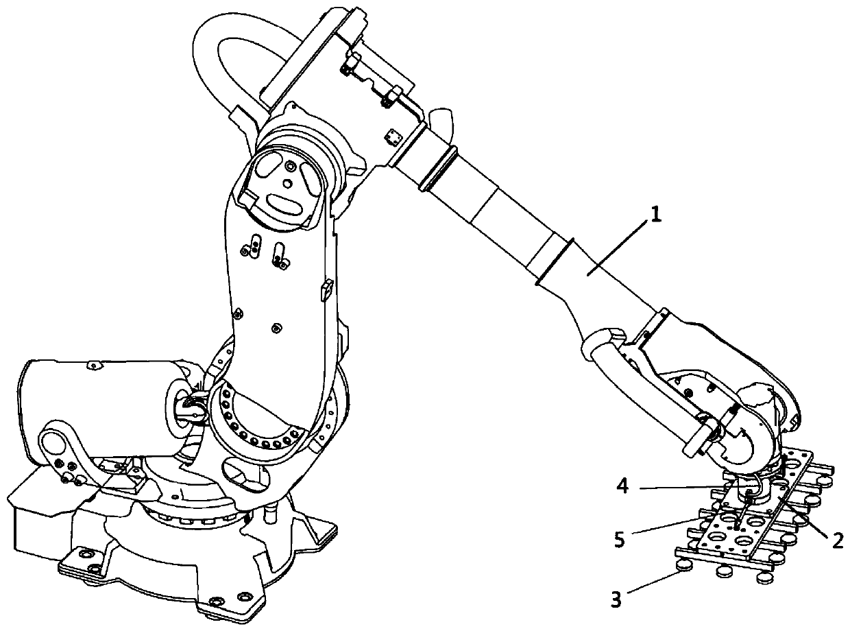
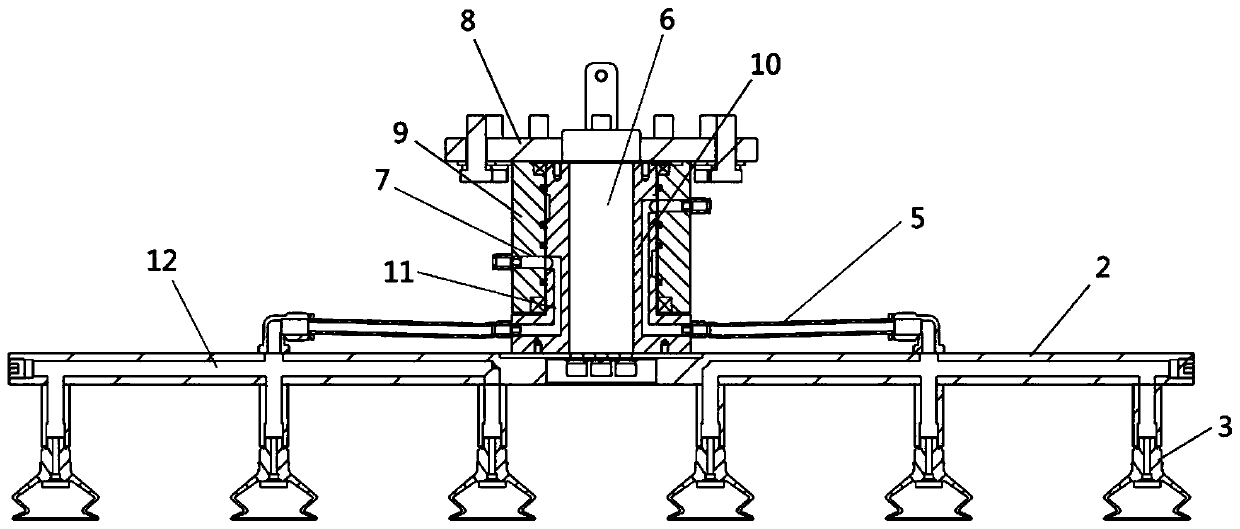
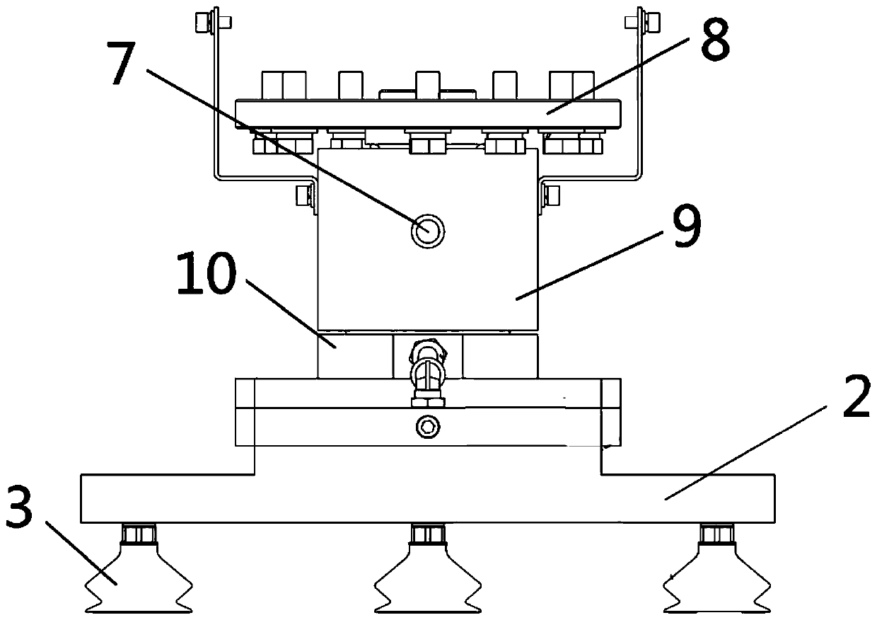
[0040] Such as figure 1 -5 shows a specific implementation of the mechanical arm rotary suction cup transfer device involved in the present invention. The mechanical arm rotary suction cup transfer device is used to transport items with suction cups 3 , and the mechanical arm rotary suction cup transfer devi...


PUM


Abstract

The invention relates to the technical field of conveying devices, in particular to a mechanical arm rotating sucker conveying device. The mechanical arm rotating sucker conveying device comprises a mechanical arm main body, a sucker assembly, an air pipeline assembly and a first air pipe, wherein the sucker assembly comprises a fixed component fixedly connected with the mechanical arm main body, a rotating component which is connected with the mechanical arm main body and rotates relative to the fixed component and a plurality of suckers which are connected with the rotating component and synchronously rotate with the rotating component; the air pipeline assembly comprises a plurality of first air pipeline structures arranged on the fixed component and a plurality of second air pipeline structures arranged on the rotating component, and the second air pipeline structures separately communicate with the suckers and an air path formed by the first air pipeline structures; and the first air pipe is connected with the first air pipeline structures of the fixed component. The service life of the mechanical arm rotating sucker conveying device is longer, economical losses can be reduced, and the production efficiency is increased.

Description

technical field [0001] The invention relates to the technical field of transmission devices, in particular to a mechanical arm rotary suction cup transmission device. Background technique [0002] Robot or manipulator grippers are usually used to grab cartons and other items. Usually, the robot gripper is directly connected to the robot flange. The air pipe of the gripper is fixed on the end of the robot wrist and on the robot gripper on the other side. The method on the robot wrist The rotation angle of Lan is 0-360° when working, the fixture will rotate with the flange of the robot, but the position of the trachea on the robot wrist is static, when the fixture is rotating, the trachea will continue to bend repeatedly, and due to gravity The reason is that the sagging and the sliding friction of the fixture body have very high requirements on the anti-flex fatigue and wear resistance of the trachea. At present, the service life of the 360° repeated rotation of the trachea i...

Claims


Application Information

Patent Timeline
Patent Type & Authority Applications(China)
IPC IPC(8): B25J15/06
CPCB25J15/0633
Inventor 郭跃平誉东明胡忠鸿刘会杰卢振乐孙雪松黄晓飞谭子平杨炎炎陈佰虎刘浩谢柳金
Owner CHINA TOBACCO GUANGXI IND
Why Eureka
Try Eureka