A Robot Vision Measuring System Based on External Tracking and Its Calibration Method

A technology of robot vision and calibration method, which is applied in the field of robot vision measurement system based on external tracking and its calibration, can solve the problems of time-consuming and laborious work, low data acquisition efficiency, and small data acquisition amount for marking point layout and cleaning, and avoids problems such as The solution results are different, the solution results are stable, and the measurement accuracy is good

Active Publication Date: 2020-07-10
HUAZHONG UNIV OF SCI & TECH
View PDF7 Cites 0 Cited by
  • Summary
  • Abstract
  • Description
  • Claims
  • Application Information

AI Technical Summary

Problems solved by technology

Contact measurement generally has high precision, but it belongs to point measurement, the data acquisition efficiency is low, and the amount of data acquisition is small
After arranging marker points, the photogrammetry system can realize batch acquisition of measuring points, and the efficiency and quantity of data acquisition have been improved to a certain extent, but most of them can only be used for the measurement of key dimensions; area array scanners or line lasers based on marker point splicing The scanner measurement solution can achieve high-efficiency and large-scale acquisition of point clouds, but the layout and cleaning of marker points is time-consuming and laborious
The above-mentioned measurement scheme that needs to arrange marker points is greatly restricted in the working conditions where marker points cannot be used or are inconvenient to arrange

Method used


Image

  • A Robot Vision Measuring System Based on External Tracking and Its Calibration Method
  • A Robot Vision Measuring System Based on External Tracking and Its Calibration Method
  • A Robot Vision Measuring System Based on External Tracking and Its Calibration Method

Examples


Embodiment Construction

[0039]In order to make the objectives, technical solutions and advantages of the present invention clearer, the present invention will be further described in detail below with reference to the accompanying drawings and embodiments. It should be understood that the specific embodiments described herein are only used to explain the present invention, but not to limit the present invention. In addition, the technical features involved in the various embodiments of the present invention described below can be combined with each other as long as they do not conflict with each other.

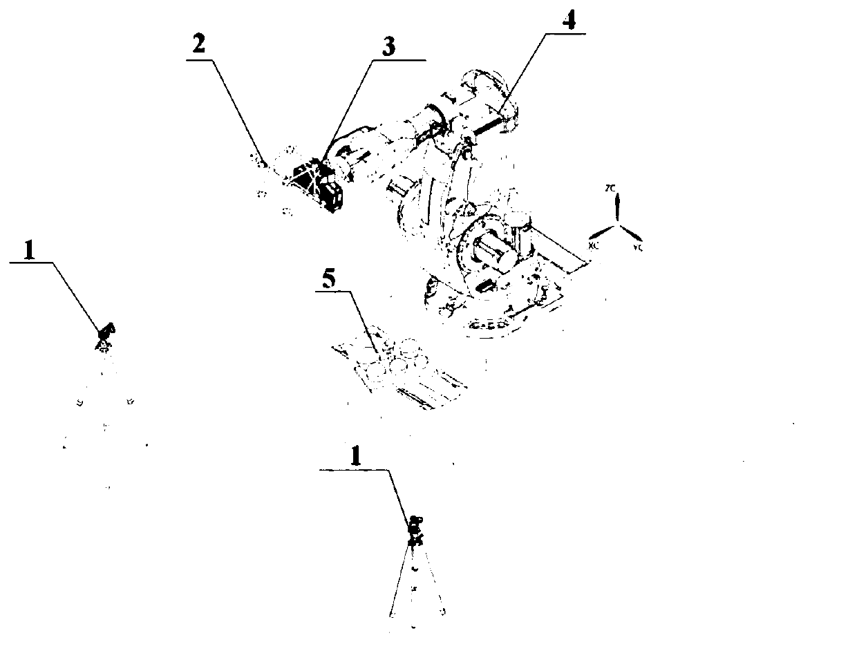
[0040] like figure 2 As shown, a robot vision measurement system based on external tracking is characterized in that, the visual measurement system includes an external tracking device 1, a three-dimensional spherical cage target 2, an area array scanner 3, an industrial robot 4 and a calibration device 5, wherein:

[0041] The area array scanner 3 is disposed at the end of the industrial robot, th...


PUM


Abstract

The invention belongs to the field of robot vision measurement, and discloses a robot vision measurement system based on external tracking and a calibration method thereof. The visual measurement system includes an external tracking device, a three-dimensional cage target, an area scanner, an industrial robot and a calibration device, the area scanner is arranged at the end of the industrial robot, and the three-dimensional cage target is arranged on the area scanner. The present invention also discloses a calibration method for the above-mentioned measurement system. By using an external tracking device and an area scanner to scan the three-dimensional spherical cage target and the calibration device respectively, two groups of data in the state of constant posture and position change and pose transformation are collected. The target data, and then establish the conversion relationship between the mutual coordinate systems, and finally use the two sets of data to calculate the conversion matrix between the area scanner coordinate system and the three-dimensional spherical cage target coordinate system. Through the present invention, different solution results may be caused by processing the same data by different people or at different times, and the stability and consistency of the calibration solution are realized.

Description

technical field [0001] The invention belongs to the field of robot vision measurement, and more particularly relates to a robot vision measurement system based on external tracking and a calibration method thereof. Background technique [0002] The measurement of large parts is widely used in digital measurement, digital processing, and digital assembly in the field of industrial manufacturing. It is one of the technical directions to realize the automation and intelligence of industrial manufacturing. [0003] The measurement of existing large parts is divided into contact and non-contact. Contact measurement includes CMM and binocular CMM; non-contact measurement mainly includes photogrammetry, area array scanner or line laser scanner measurement scheme based on marker point splicing. Contact measurement generally has high accuracy, but it belongs to point measurement, with low data acquisition efficiency and small amount of data acquisition. After arranging the marking ...

Claims


Application Information

Patent Timeline
Patent Type & Authority Patents(China)
IPC IPC(8): G01B11/00
CPCG01B11/002
Inventor 李文龙彭泽龙蒋诚王刚
Owner HUAZHONG UNIV OF SCI & TECH
Why Eureka
Try Eureka