
Pixel circuit, driving method and display device

A pixel circuit and driving method technology, which is applied in the display field, can solve the problems of high power consumption and reduce the life of light-emitting units, and achieve the effects of increasing life and reducing power consumption

Active Publication Date: 2019-09-20
BOE TECH GRP CO LTD
View PDF6 Cites 6 Cited by
  • Summary
  • Abstract
  • Description
  • Claims
  • Application Information

AI Technical Summary

Problems solved by technology

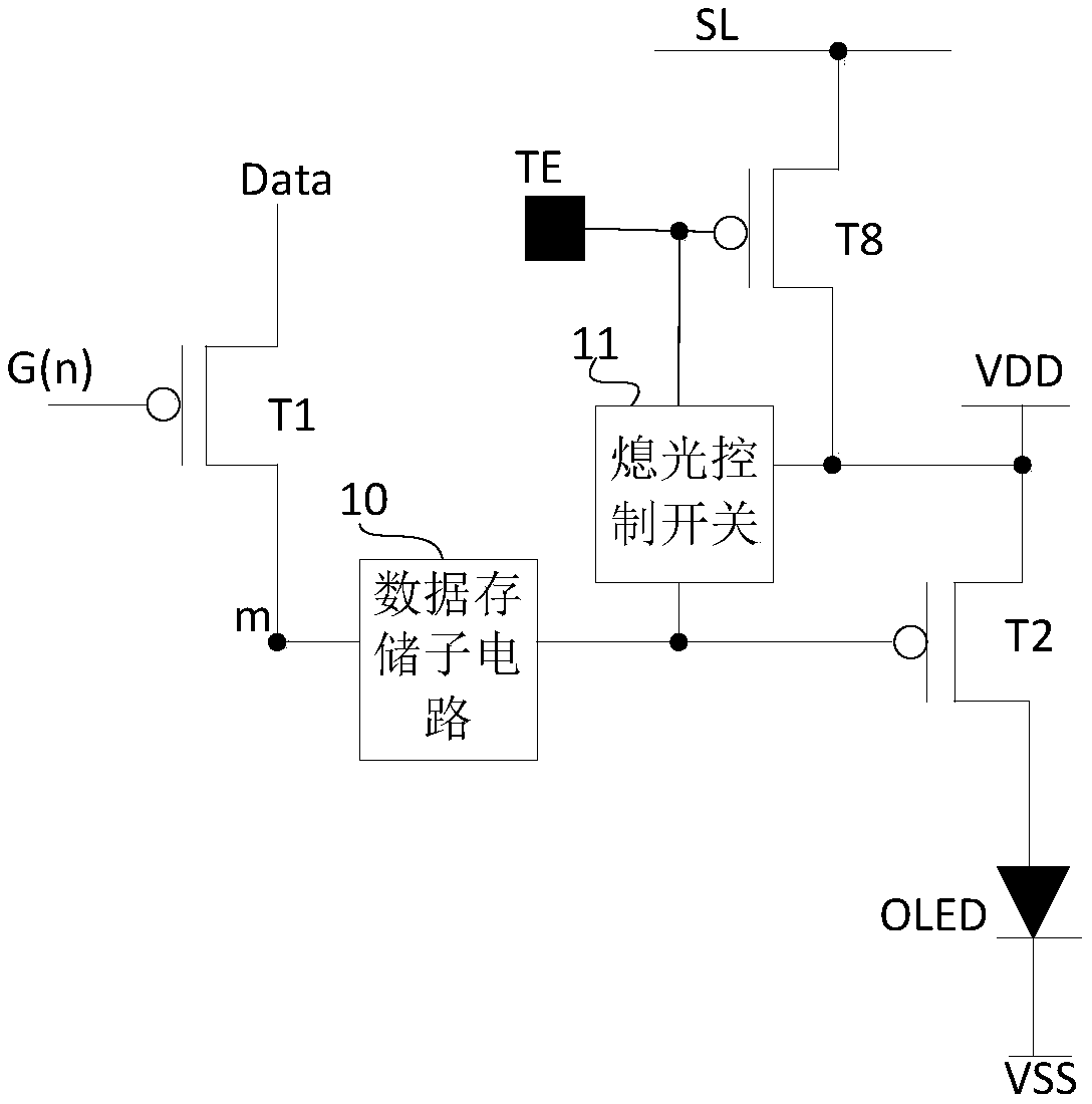
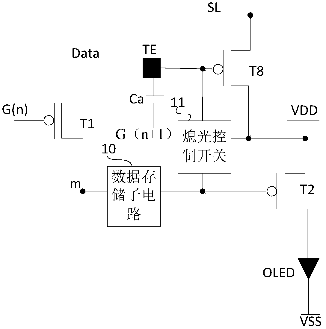
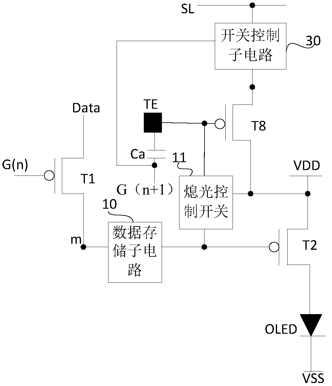
[0003] The main purpose of the present invention is to provide a pixel circuit, a driving method and a display device to solve the problems in the prior art that the light-emitting unit still keeps emitting light in the touch area, which leads to high power consumption and shortens the life of the light-emitting unit

Method used


Image

  • Pixel circuit, driving method and display device
  • Pixel circuit, driving method and display device
  • Pixel circuit, driving method and display device

Examples


specific Embodiment approach

[0119] According to a specific implementation manner, the initialization subcircuit may include a first initialization transistor and a second initialization transistor;

[0120] The control pole of the first initialization transistor is connected to the initialization control line, the first pole of the first initialization transistor is connected to the second pole of the input transistor, and the second pole of the first initialization transistor is connected to the The connection of the initialization voltage terminal;

[0121] The control electrode of the second initialization transistor is connected to the second gate line, the first electrode of the second initialization transistor is connected to the second electrode of the input transistor, and the second electrode of the second initialization transistor is connected to the second gate line. The initialization voltage terminal is connected.

Embodiment approach

[0122] According to another specific implementation manner, the initialization subcircuit may include an initialization transistor; the initialization transistor is a double-gate transistor;

[0123] The first control electrode of the initialization transistor is electrically connected to the initialization control line, the second control electrode of the initialization transistor is electrically connected to the second gate line, and the first electrode of the initialization transistor is electrically connected to the input transistor The second pole of the initialization transistor is electrically connected to the initialization voltage terminal.

[0124] In a specific implementation, the initialization sub-circuit may include two initialization transistors, or only one initialization transistor (when only one initialization transistor is included, the initialization transistor is a double-gate transistor), and initialization control can be realized.

[0125] Such as Figu...


PUM


Abstract

The invention provides a pixel circuit, a driving method and a display device. The pixel circuit includes: an input transistor; a display driving transistor; a data storage sub-circuit configured to couple a data signal transmitted to a second pole of the input transistor to a control pole of the display driving transistor; the pixel circuit further comprises a touch electrode, a touch driving transistor and a light-extinguishing control switch, wherein one end of the light-extinguishing control switch is connected to the power line, the other end of the light-extinguishing control switch is connected to a control electrode of the display driving transistor, the control end of the light-extinguishing control switch is connected to the touch electrode, and the light-extinguishing control switch is configured to control the communication state between the power line and the control electrode of the display driving transistor according to the potential of the touch electrode. The invention solves the problems that the power consumption is high and the service life of the light-emitting unit is shortened due to the fact that the light-emitting unit still keeps emitting light in the touch area in the prior art.

Description

technical field [0001] The present invention relates to the field of display technology, in particular to a pixel circuit, a driving method and a display device. Background technique [0002] The touch function is more and more widely used in various display panels, especially mobile displays. The display and touch functions can be integrated and completed in one process instead of two processes, so it not only has low cost Advantages, but also make the process simple, and the display touch panel is thinner and lighter. A touch electrode is integrated in an existing pixel circuit combined with a touch function, and when the touch electrode is touched, the light-emitting unit in the pixel circuit still emits light, so the power consumption is high and the life of the light-emitting unit is short. Contents of the invention [0003] The main purpose of the present invention is to provide a pixel circuit, a driving method and a display device, which solve the problems in the ...

Claims


Application Information

Patent Timeline
Patent Type & Authority Applications(China)
IPC IPC(8): G09G3/3208G06F3/041
CPCG06F3/041G09G3/3208
Inventor 刘伟星王铁石徐智强秦纬李胜男彭宽军李小龙
Owner BOE TECH GRP CO LTD
Learn More