
Radio frequency coaxial connector

A radio frequency coaxial and connector technology, applied in the direction of connection, two-part connection device, parts of the connection device, etc., can solve the problems of incomplete mating of radio frequency plug and radio frequency socket, damaged signal transmission, affecting signal transmission, etc. , to achieve the effect of simple and convenient plugging and unplugging operation, not easy to be damaged, and small impedance change

Pending Publication Date: 2019-09-20
SHANGHAI AEROSPACE SCI & IND ELECTRIC APPLIANCE RES INST
View PDF0 Cites 1 Cited by
  • Summary
  • Abstract
  • Description
  • Claims
  • Application Information

AI Technical Summary

Problems solved by technology

[0004] Therefore, during the use of the current RF coaxial connector, the RF plug and the RF socket must be fully inserted, otherwise it will easily affect the signal transmission
However, in high-frequency high-speed lines, a large number of RF transmission lines are usually distributed in arrays, which usually integrates multiple RF coaxial connectors; and the RF plug and RF socket in a single RF coaxial connector are fully plugged and operated easily. It can be achieved, but it is easy to plug and connect most RF coaxial connectors at one time, and the RF plugs and RF sockets in several RF coaxial connectors are prone to incomplete mating, which makes subsequent debugging necessary , adjustment, re-mating and other operations are not only troublesome to operate, but also easily cause damage to signal transmission

Method used


Image

  • Radio frequency coaxial connector
  • Radio frequency coaxial connector
  • Radio frequency coaxial connector

Examples


Embodiment Construction

[0021] In order to make the object, technical solution and advantages of the present invention clearer, the present invention will be further described in detail below in conjunction with the accompanying drawings and embodiments. It should be understood that the specific embodiments described here are only used to explain the present invention, not to limit the present invention.

[0022] In the description of the present invention, it should be noted that unless otherwise specified, the meaning of "plurality" is two or more; the terms "upper", "lower", "left", "right", "inner ", "outside", "front end", "rear end", "head", "tail", etc. indicate the orientation or positional relationship based on the orientation or positional relationship shown in the drawings, and are only for the convenience of describing the present invention and Simplified descriptions, rather than indicating or implying that the device or element referred to must have a particular orientation, be construc...


PUM


Abstract

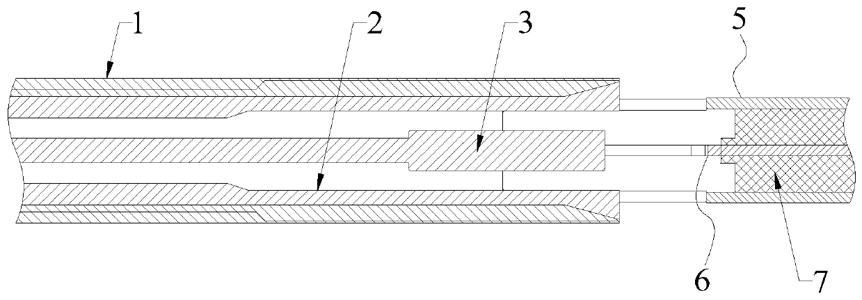
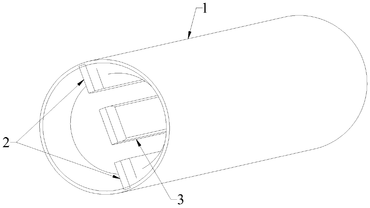
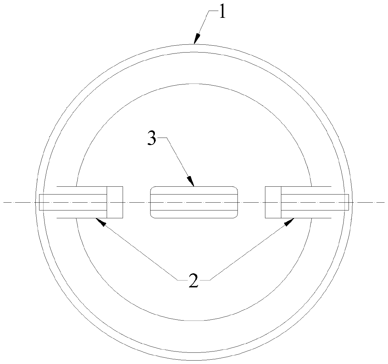
The invention relates to a radio frequency coaxial connector, which includes a radio frequency plug and a radio frequency socket. The radio frequency plug includes a tubular plug outer conductor. Multiple first conductor plates are arranged along the axis of the plug outer conductor inside the plug outer conductor. A second conductor plate is fixedly arranged at the central axis of the plug outer conductor. The radio frequency socket includes a tubular socket shell. First slots matching the first conductor plates are arranged at the front end of the socket shell. A tuning-fork-shaped socket inner conductor is arranged at the central axis of the socket shell. A second slot matching the second conductor plate is arranged at the head end of the socket inner conductor. An insulating sleeve fills the gap between the tail of the socket inner conductor and the inner wall of the socket shell. When the radio frequency plug is plugged into the radio frequency socket of the radio frequency coaxial connector, the plugging error is within 3mm, the impedance change is small, and the signal transmission is almost free from interference. The radio frequency coaxial connector has high fault tolerance, and is suitable for large-scale synchronous application.

Description

technical field [0001] The invention relates to a radio frequency coaxial connector and belongs to the technical field of radio frequency connectors. Background technique [0002] RF coaxial connectors are generally considered to be a component that is attached to a cable or installed on an instrument, as a component that is electrically connected or separated by a transmission line. [0003] During the use of the current RF coaxial connector, if the RF plug and the RF socket are not plugged in place, that is, there is an error between the actual insertion position of the RF plug and the RF socket and the position where the RF plug and the RF socket are fully inserted, for example, For a single RF transmission line, the RF coaxial connector is mainly not fully inserted, so the impedance at the RF coaxial connector can reach 70-80Ω, for example, the actual insertion position of the RF coaxial connector and the complete insertion The error between positions is 3mm, then the i...

Claims


Application Information

Patent Timeline
Patent Type & Authority Applications(China)
IPC IPC(8): H01R24/44H01R13/04H01R13/46H01R13/11H01R13/502H01R13/6474
CPCH01R24/44H01R13/04H01R13/46H01R13/113H01R13/502H01R13/6474H01R24/60H01R13/642
Inventor 肖顺群
Owner SHANGHAI AEROSPACE SCI & IND ELECTRIC APPLIANCE RES INST
Learn More